Make DIY Homework Writing Machine at Home


Introduction: Make DIY Homework Writing Machine at Home

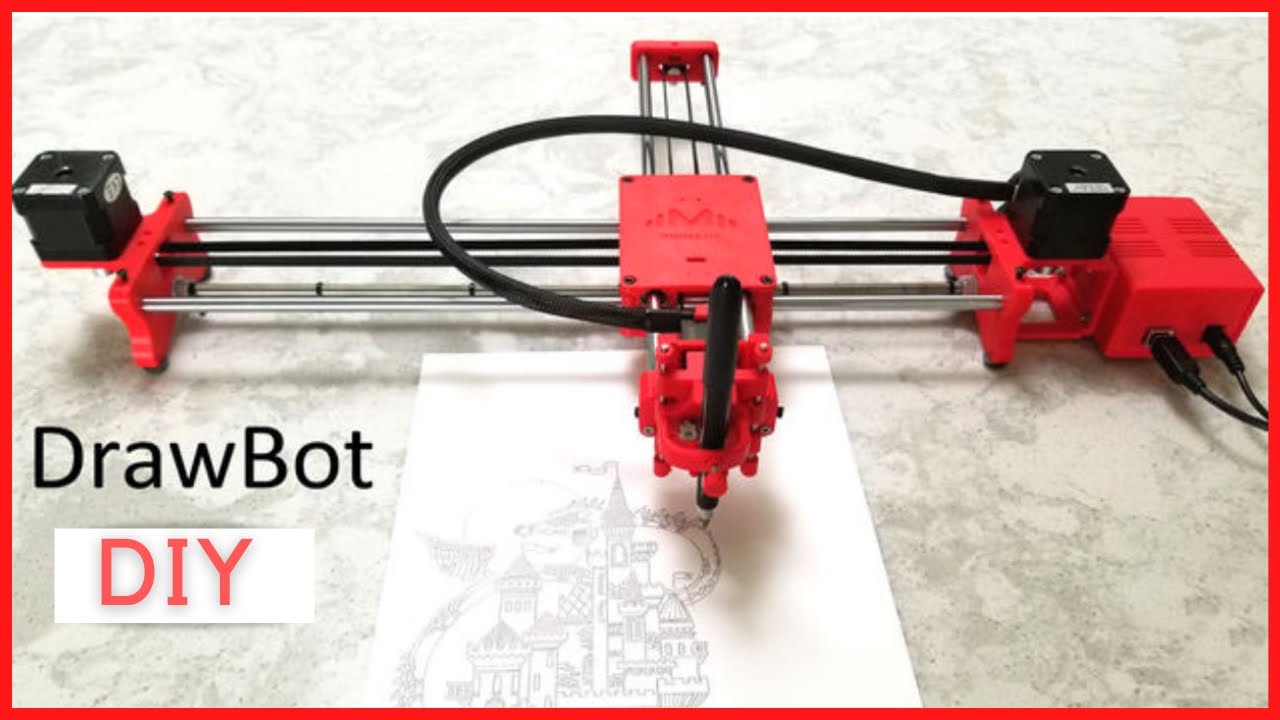
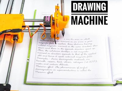
Drawing Robot/Pen Plotter/Drawing Machine is an Open Hardware version of the famous machine AxiDraw which it is a pen plotter, capable of writing or drawing on almost any flat surface. It can write with pens, permanent markers, pencils, and other writing implements to handle an endless variety of applications.
Its unique design features a writing head that extends beyond the machine, making it possible to draw on objects bigger than the machine itself. The biggest advantage of the machine is that it can be placed over the book because of the core XY extending design of the machine.
This Drawing Robot/Pen Plotter/Drawing Machine is similar to the commercially available AxiDraw. It is powered by an Arduino Uno controller, uses a CNC Shield, and GRBL firmware
The cost to build the Drawing Robot is between $75 depending on where you buy your parts and whether you already own some of the parts such as the Arduino.
You can find all of my projects on https://www.diyprojectslab.com/
Maximum drawing area 24 * 30 CM.
Thank You NextPCB This project is successfully completed because of the help and support from NextPCB. Guys if you have a PCB project, please visit their website and get exciting discounts and coupons.
Free shipping 0$ PCB Prototype: https://www.nextpcb.com/pcb-quote?act=2&code=Romeo...
Thanksgiving Christmas lucky draw 100% win: https://www.nextpcb.com/christmas-lucky-draw?code...
Step 1: Parts and Materials Required

2 x Nema 17 Stepper Motors Amazon.com
2 x Linear Rod M8 x 450mm for X Axis Amazon.com
2 x Linear Rod M8 x 350mm for Y Axis Amazon.com
2 x Linear Rod 3mm for Z Axis (you can get it from old CDROM)
1 x Threaded Rod M8 x 480mm8 x LM8UU Bearings Amazon.com
1 x Servo Sg901 x Spring 5m (from ball point pen) Amazon.com
2 x GT2 Pulley, 16 teeth Amazon.com
5 x Bearing 624zz Amazon.com
1 x 2000mm GT2 belt Amazon.com
1 x Arduino Uno Amazon.com
1 x CNC Shield Amazon.com
2 x A4988 Stepper driver with heatsink Amazon.com
6 x Jumpers Amazon.com
1 x 12V 2A Power Supply Amazon.com
- 4 x 5/16in-18
- 13 x Phillips M3-0.5 x 16mm
- 4 x Phillips M3-0.5 x 6mm
- 5 x Phillips M4-0.7x 35mm
- 1 x Hex M3-0.5 x 20mm
- 4 x 5/16in washer
- 4 x M3 washers
Step 2: 3D Printing

Download the files from Thingiverse
Open the 3D models in Cura or any other slicer.
Use 75% infill on all the parts (An infill of 70 – 100% will work as well)
Printed all the parts with 0.10 – 0.20 mm layer height
Printed with PLA
Use supports on the Penholder, Slider, X_Support_L and the X_Support_R
Note: The longest part took around 10hrs and the shortest took 30 minutes to print
PLA is fine for this design. I print at 200C on BuildTak. None of the parts require rafts or brims. I suggest supports only for the pen holder and the Z axis end plate which is standing up.
Step 3: Assemble the X-Axis

Remember that you need (2) 350mm and (2) 450mm long linear rods
Take the (2) 450mm linear rods and insert them into either x-support part
- Use may need to use a round file to smooth out the holes that you insert them in
- Also, you can use a rubber mallet to help insert the rods
Now take the threaded rod and insert it in the hole below. Feed a 5/16in washer and 5/16in nut on both sides of the x-support part
Step 4: Assemble the X-Axis Bearing

Now you want to push the LM8UU bearings into their place on the top and bottom clamshell (The top and bottom clamshell take (4) bearings each)
Take (4) 624zz bearings and push them through the 3D-printed idler pulleys. Leave the 5th bearing for later when you assemble the Y-axis
Assemble the X-Axis (Carriage)
- Get (4) M3-0.5 x 20mm screws, (4) M3 nuts, (4) M3 washers and (4) 624zz bearings with the idler pulleys installed
- Take one screw and feed a washer through it, the washer will rest on the bearing. The nut will be at the bottom of the carriage, which will secure the bearing in place
Assemble the X-Axis (X-Support)
- Slide the clamshell through the 450mm (X-axis) linear rods
- Use a rubber mallet again to attach the last X-support on the linear rods
- Make sure that the rods stick out equally on both sides
- Slide the other end of the threaded rod through the hole on the X-support
- Put on the last set of nuts and washers to hold the X-support in place
- Now that the X-axis is complete, you can use (2) Phillips M3-0.5 x 16mm screws per X-support to help keep the linear rods from sliding
Step 5: Assemble the Y-Axis

- Take the (2) 350mm linear rods and insert them the Y-back piece by using a rubber mallet
- Get (1) M4-0.5 x 35 screw, (1) M4 nut and the 5th 624zz bearing
- Get (2) M3-0.5 x 16 screws to secure the linear rods
- Slide in the bearing when inserting the screw through the Y-back piece
- Slide the the linear rods/Y-back piece through the LM8UU bearings and attach the Y-front piece using a rubber mallet
Step 6: Assemble the X-Y Axis (Belt)

- Use a pair of needle nose pliers to help guide the GT2 belt more easily through the clamshell
- Take the two ends of the belt and slide them through the “teeth” on the Base Slider
- The belt should be tight and not loose
- Note that once the GT2 belt is on, it is normal for the clamshell not to move easily
Step 7: Assemble the Z-Axis

- Get (2) 3mm linear rods and the following 3D printed parts (Slider, Pen Holder, Base Slide, 3MM Metric Thumb Screw)
- Get (1) Hex M3-0.5 x 20mm screw and the Metric Thumb Screw and push them together. Use superglue to keep it together.
- Get (3) M3-0.5 x 16mm screws which you will use the secure the Base Slide to the Y-Front part. You may need to use (3) M3-0.5 nuts in order to hold it in place
- Push the Slider and Pen Holder together to make one piece
- Now take that new part and the (2) 3mm linear rods and slide the rods through the holes. Place a small spring in between the two parts so there is a little bit of pressure to lift the Slider. You may need to cut the spring a bit until there is an adequate amount of pressure on the slider.
Step 8: ELECTRONICS

ELECTRONICS
i prefer you can use Arduino uno CNC Shield
Ready to your all circuit
1) 4pcs A4988 Stepper Motor Driver
2) Expansion Board A4988 Driver
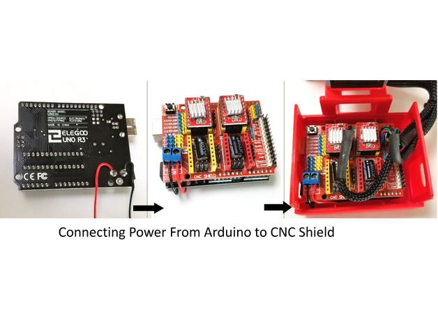
3)Arduino UNO First of all take hit sink and stick on A4988 motor Driver.
4pcs A4988 Stepper motor driver connect on expansion board A4988 driver module, then connect the arduino with expansion board and connect all wiring The shield also has a built-in micro stepping control - meaning that instead of using full steps or half steps like a large CNC would do, we can make the motors move by 1/16 or 1/32 of a step to make the laser move with the maximal precision possible. However, the motors will consume more electricity: they will get hot quicker.
To use the micro stepping modes, short some of the mode pins together. Different combinations give different resolutions. Take a look at the chart for the different configurations possible. When the shield is programmed, add the A4988 drivers to it and wire up the rest of the electronics.
To find the coils of the stepper motors, use a multimeter. If there's resistance between the two wires, you have a coil. On the schematic, the coils are represented by two wires of the same color.
Step 9: SOFTWARE

Inkscape which is the graphics design software (draw or import graphics)
Inkscape MI GRBL Extension (convert graphics to G-Code)Universal G Code Sender (sends the G-Code to the robot causing drawing motion)GRBL which is the Arduino firmware (programmed into the Arduino Uno)
Arduino: https://www.arduino.cc/en/software
Universal G-code sender: https://winder.github.io/ugs_website/...
Inkscape: https://inkscape.org/release/inkscape..
4xiDraw & km laser: https://drive.google.com/file/d/1YO8-...
Processing: https://processing.org/download/
drawing to G-code processing: https://drive.google.com/file/d/1PIFx...
watch video for full setup
Step 10: Drawing Machine at Work
Recommendations

Books and Bookshelves Contest

Make it Resilient

Big and Small Contest

- Online Text to STL
- 3D Printed Soldering Helper
- 3D Printed Coin Vault
- 3D Printed FLARE GUN (PROP/REPLICA) MULTI PART
- 3D Printed Mini Container with PET Bottle Cap Size
TEST 3D PRINTS
Easy & Fun Things to 3D Print
How To Make DIY Pen Plotter / Homework Writing Machine at Home
This Drawing Robot/Pen Plotter/Drawing Machine is similar to the commercially available AxiDraw. It is powered by an Arduino Uno controller, uses a CNC Shield, and GRBL firmware.
The cost to build the Drawing Robot is between $75 and $100 depending on where you buy your parts and whether you already own some of the parts such as the Arduino.
Parts and Materials Required
- 2 x Nema 17 Stepper Motors
- 2 x Linear Rod M8 x 450mm for X Axis
- 2 x Linear Rod M8 x 350mm for Y Axis
- 2 x Linear Rod 3mm for Z Axis (you can get it from old CDROM)
- 1 x Threaded Rod M8 x 480mm
- 8 x LM8UU Bearings
- 1 x Servo Sg90
- 1 x Spring 5m (from ball point pen)
- 2 x GT2 Pulley, 16 teeth
- 5 x Bearing 624zz
- 1 x 2000mm GT2 belt
- 1 x Arduino Uno
- 1 x CNC Shield
- 2 x A4988 Stepper driver with heatsink
- 6 x Jumpers
- 1 x 12V 2A Power Supply
- 4 x 5/16in-18
- 13 x Phillips M3-0.5 x 16mm
- 4 x Phillips M3-0.5 x 6mm
- 5 x Phillips M4-0.7x 35mm
- 1 x Hex M3-0.5 x 20mm
- 4 x 5/16in washer
- 4 x M3 washers
3D Printing
- Download the files from Thingiverse
- Open the 3D models in Cura or any other slicer(Sli3er, Simplify 3D, etc.)
- Use 75% infill on all the parts (An infill of 70 – 100% will work as well)
- Printed all the parts with 0.10 – 0.20 mm layer height
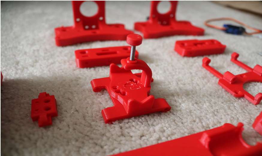
- Printed with Hatchbox Red PLA
- Use supports on the Penholder, Slider, X_Support_L and the X_Support_R
Note: The longest part took around 9hrs and the shortest took 30 minutes to print
3D Printed Parts
Cut your Linear Rods
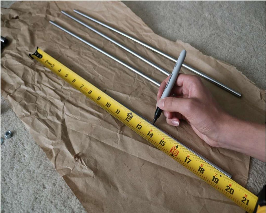
Use a measuring tape and sharpie to mark the spots where the rods need to be cut
- Use a vise to hold the rods in place when you cut them
- Remember that you need (2) 350mm and (2) 450mm long linear rods
- On the threaded rod, mark your cutting point at 470mm
Assemble the X-Axis (Linear/Threaded Rods)
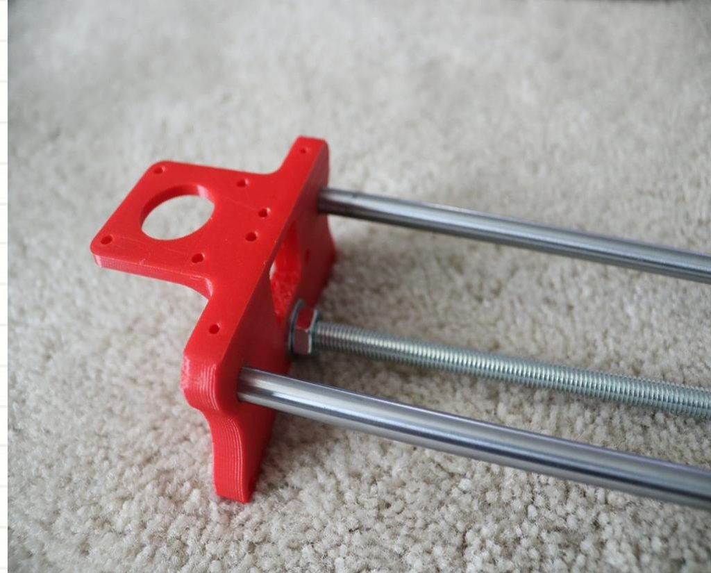
Take the (2) 450mm linear rods and insert them into either x-support part
- Use may need to use a round file to smooth out the holes that you insert them in
- Also, you can use a rubber mallet to help insert the rods
Now take the threaded rod and insert it in the hole below. Feed a 5/16in washer and 5/16in nut on both sides of the x-support part
Assemble the X-Axis (Bearings)
Now you want to push the LM8UU bearings into their place on the top and bottom clamshell (The top and bottom clamshell take (4) bearings each)
Take (4) 624zz bearings and push them through the 3D-printed idler pulleys. Leave the 5th bearing for later when you assemble the Y-axis
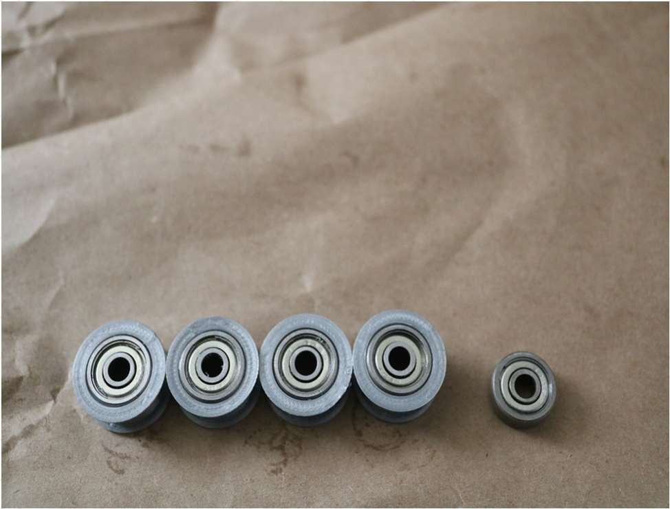
Assemble the X-Axis (Carriage)
- Get (4) M3-0.5 x 20mm screws, (4) M3 nuts, (4) M3 washers and (4) 624zz bearings with the idler pulleys installed
- Take one screw and feed a washer through it, the washer will rest on the bearing. The nut will be at the bottom of the carriage, which will secure the bearing in place

Assemble the X-Axis (X-Support)
- Slide the clamshell through the 450mm (X-axis) linear rods
- Use a rubber mallet again to attach the last X-support on the linear rods
- Make sure that the rods stick out equally on both sides
- Slide the other end of the threaded rod through the hole on the X-support
- Put on the last set of nuts and washers to hold the X-support in place
- Now that the X-axis is complete, you can use (2) Phillips M3-0.5 x 16mm screws per X-support to help keep the linear rods from sliding
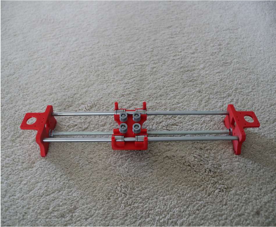
Assemble the X-Axis (Stepper Motors)
- Use an appropriate sized allen wrench to attach the 16 teeth pulleys on the stepper motor shafts
- Flipping the entire chassis around will make it easier to attach the stepper motors
- Use (8) M3-0.5 x 6mm screws and a Phillips screwdriver to attach the (2) stepper motors
Assemble the Y-Axis (Clamshell)
(Optional if you have problems keeping belt on bearings)
- Grab (4) M4-0.5 x 35mm screws and (4) M4 nuts
- Make sure that you have the (4) idler pulleys ( Download from Thingiversa ) and the (4) washers printed
- Insert the washers in between the two clamshells, with a screw in between
- Screw the top and bottom clamshells together
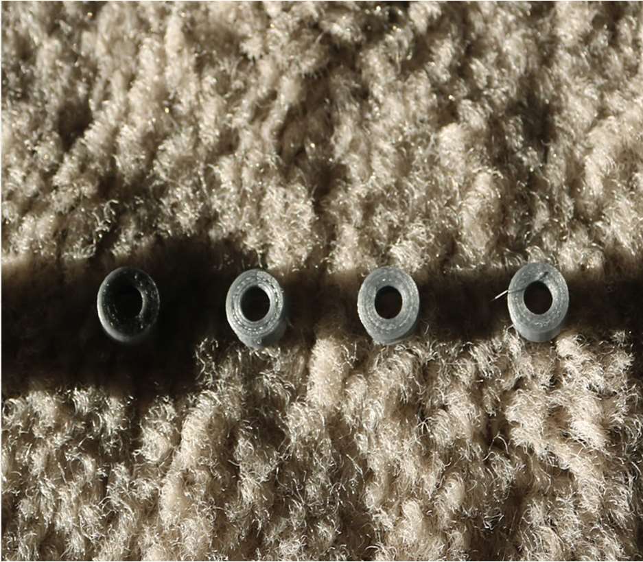
Assemble the Y-Axis (Y- Back/Front)
- Take the (2) 350mm linear rods and insert them the Y-back piece by using a rubber mallet
- Get (1) M4-0.5 x 35 screw, (1) M4 nut and the 5th 624zz bearing
- Get (2) M3-0.5 x 16 screws to secure the linear rods
- Slide in the bearing when inserting the screw through the Y-back piece
- Slide the the linear rods/Y-back piece through the LM8UU bearings and attach the Y-front piece using a rubber mallet
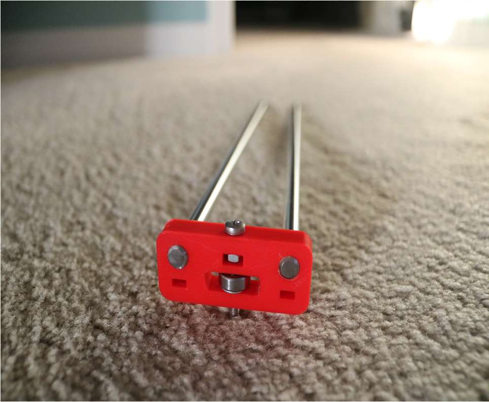
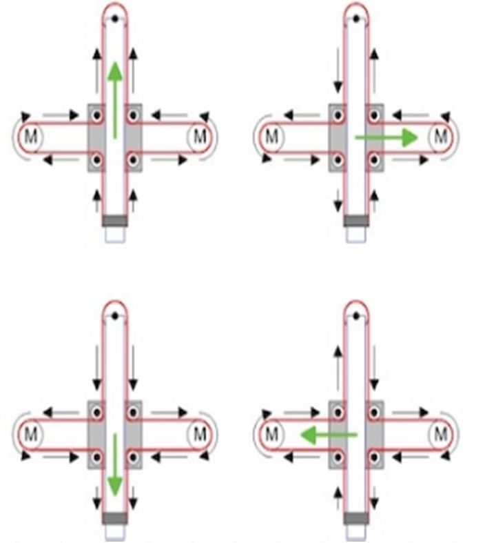
Assemble the X-Y Axis (Belt)
- Use a pair of needle nose pliers to help guide the GT2 belt more easily through the clamshell
- Take the two ends of the belt and slide them through the “teeth” on the Base Slider
- The belt should be tight and not loose
- Note that once the GT2 belt is on, it is normal for the clamshell not to move easily
Belt Diagram
Assemble the Z-Axis
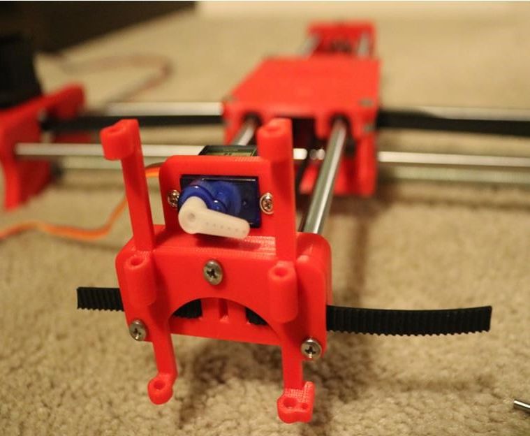
- Get (2) 3mm linear rods and the following 3D printed parts (Slider, Pen Holder, Base Slide, 3MM Metric Thumb Screw)
- Get (1) Hex M3-0.5 x 20mm screw and the Metric Thumb Screw and push them together. Use superglue to keep it together.
- Get (3) M3-0.5 x 16mm screws which you will use the secure the Base Slide to the Y-Front part. You may need to use (3) M3-0.5 nuts in order to hold it in place
- Push the Slider and Pen Holder together to make one piece
- Now take that new part and the (2) 3mm linear rods and slide the rods through the holes. Place a small spring in between the two parts so there is a little bit of pressure to lift the Slider. You may need to cut the spring a bit until there is an adequate amount of pressure on the slider.
Step By Step Video
The Original Instructions by Henry Arnold Jonathan K
- 3D Printed Hairy Lion →
12 thoughts on “ How To Make DIY Pen Plotter / Homework Writing Machine at Home ”
i constructed all the machine but when i press X+ the both X and Y axis are moving what is the problem
double check the steppers wiring
Have you solved it? I have the same problem with my machine, when I press X+, it’s necessary both motors move at same time, but, only one of them move…
Did you solve this problem?
Same problem how to solve ,?
Is it true that you didn’t use the microswitches in the final design?
Hello how to co figurę this machine to RUN on GRBL. What I mean is that GRBL interprets commands for x axis and y axis independently and if I look on your belt diagram it looks like both Motors have to run at the same time in order to move the carriage along y axis… How did you do that?
Have you solved it?
Thank you, thank you. It’s a very good built.
Is it possible to modify it to draw using brush ang oil based paint ?
Could you please tell what software/plug in and which version do you use to generate g-code for this machine?
Hello, what is the width of your belt? 6mm or 10mm? Thanks!
Leave a Reply Cancel reply
Your email address will not be published. Required fields are marked *
Save my name, email, and website in this browser for the next time I comment.

News the global electronics community can trust

The trusted news source for power-conscious design engineers

Supply chain news for the electronics industry

The can't-miss forum engineers and hobbyists

The electronic components resource for engineers and purchasers

Design engineer' search engine for electronic components

Product news that empowers design decisions

The educational resource for the global engineering community

The learning center for future and novice engineers

The design site for electronics engineers and engineering managers

Where makers and hobbyists share projects

The design site for hardware software, and firmware engineers

Where electronics engineers discover the latest tools

Hardware design made easy

Brings you all the tools to tackle projects big and small - combining real-world components with online collaboration

Circuit simulation made easy

A free online environment where users can create, edit, and share electrical schematics, or convert between popular file formats like Eagle, Altium, and OrCAD.

Transform your product pages with embeddable schematic, simulation, and 3D content modules while providing interactive user experiences for your customers.

Find the IoT board you’ve been searching for using this interactive solution space to help you visualize the product selection process and showcase important trade-off decisions.

A worldwide innovation hub servicing component manufacturers and distributors with unique marketing solutions
SiliconExpert provides engineers with the data and insight they need to remove risk from the supply chain.

Transim powers many of the tools engineers use every day on manufacturers' websites and can develop solutions for any company.
Search EEWeb
- Newsletters
- Internal/External
- Embedded Microstrip
- Symmetric Stripline
- Asymmetric Stripline
- Wire Microstrip
- Wire Stripline
- Edge-Coupled Microstrip
- Edge-Coupled Stripline
- Broadside Coupled Stripline
- Twisted Pair
- RF Unit Converter
- Online SPICE Simulator
- Schematic Converter/Viewer
- Schematic Capture Tool
- Standard Values
- Magnetic Field Calculator
- Wire Self Inductance
- Parallel Wires
- Wire over Plane
- Rectangle Loop
- Broadside-Coupled Traces
- Edge-Coupled Traces
- Engineering Paper (Printable PDF)
- Log-Log Graph Paper (PDF Download)
- Semi-Log Graph Paper (PDF Download)
- Smith Chart Graph Paper (PDF Download)
- Math Reference Sheets Overview
- Algebra Reference Sheet
- Geometry Reference Sheet
- Trigonometry Definitions and Functions
- Trigonometry Rules, Laws, and Identities
- Calculus Derivatives, Rules, and Limits
- Calculus Integrals Reference Sheet
- Online Basic Calculator
- Scientific Calculator
- Tech Communities
- Analog Design
- Power Design
- Digital Design
- Embedded Systems
- Test & Measurement
- Electromechanical
- Passive Components
- Design Library
- Extreme Circuits
- Magazines Archive
- Design Contest
- Homework Writing Machine

This homework writing machine project features a DIY writing machine that uses a typical pen. It can do outline writing and digital signature or even a real text. The main system uses a 2 axis stepper motor driver board with Nema stepper motors and Mg90S Metal Gear Servo control.
The 2 axis stepper motor driver board serves as the main controller. It organizes the motor drivers connection that best fit for the writing machine operation. This writing machine uses threaded rod rotated by nema 17 stepper motors for X-axis and Y-axis movements on the surface, while a Mg90S metal gear servo is used in the pen stand that moves the pen perpendicular to the writing surface. The movements of the motor are synchronized and quite accurate provided that it is assisted by a well-made writing machine frame structure with mixed of wood and acrylic materials.
This project is suitable for embedded development hence it can accomplished digital writing activity. It is also a good reference for DIY text and figure printing provided that it can draw specific figures.
Sources: How to Make Homework Writing Machine at home
Other Related Topics
- Building an Audio-Reactive Music Box
- Go Kart / Electric Car using PVC Pipe
Join the Conversation!
One reply to “homework writing machine”.
sir I am a student of MS electrical power engineering and my thesis are just close to starting but I am confused about topic selection. my area of interest is RENEWABLE ENERGY TECHNOLOGY. please sir help me in topic selection
Add Comment Cancel reply
You must be logged in to post a comment.
This site uses Akismet to reduce spam. Learn how your comment data is processed .
- FarhnSh1d 2024-04-03 02:40:00 1. Energy Source Availability: Identify available energy sources such as solar, wind, vibration, thermal gradients, or ambient RF signals. Choose a technology capable of effectively capturing and converting this energy into usable electrical power. 2. Energy Density and Power Output: Assess the energy density and power output of each potential source to determine if it can meet the application's power requirements, considering factors like sensor power consumption and duty cycle. 3. Environmental Conditions: Evaluate the environmental conditions of the remote location, including temperature extremes, humidity, and exposure to elements. Choose a technology that can withstand these conditions and operate reliably...
- FarhnSh1d 2024-04-03 02:39:02 Reducing the output power of an ultrasonic Piezo Ceramic disc from 35 watts to 10 watts by adjusting the control board is possible but entails several considerations: Effectiveness and Performance Lowering power may compromise the effectiveness of the ultrasonic device, potentially reducing its ability to achieve desired results like cleaning or atomization. Reduced power might lead to weaker vibrations, impacting performance, especially if the device operates away from its optimal resonance frequency. Durability and Lifespan Lowering power could potentially increase the device's lifespan by reducing stress on the piezo ceramic disc. However, extreme power reductions may lead to inadequate vibrations...
- forlinxembedded 2024-03-21 04:05:55 Hello Erdem, It's interesting to learn about the differences in electric pole usage between countries. In many countries, wooden poles are commonly used due to their availability, cost-effectiveness, and ease of installation. However, in regions with higher load requirements like Turkey, stronger poles are necessary to support the infrastructure. In the USA and some European countries, wooden poles are reinforced and treated to withstand the required loads. Additionally, alternative materials like steel and concrete are also used for electric poles in various applications. If you're interested in learning more about electric pole types and standards in different countries, I recommend...
- Lumispot 2024-03-04 11:00:10 Microcontroller For a project like yours, the choice of a microcontroller (MCU) largely depends on the complexity of the device, the number of input/output peripherals you need (like GPIOs for the sensor, speaker, LED lights, and the green light indicator), and any additional features you might require (such as PWM outputs for LED dimming or speaker volume control). Arduino Uno is a robust choice for beginners and prototypes. It's based on the ATmega328P and offers a good balance of GPIO pins, is easy to program, and has extensive community support. Arduino Nano or Arduino Micro could be more suitable for...
- richard-gabric 2024-03-04 11:00:01 You are setting yourself up to kill yourself, or at least to take an eye out. You don't say what DC voltage you need, the voltage you would get from directly applying the mains to a bridge rectifier were typically used, for example, to supply the input to a flyback switch mode power supply, where the switching transformer provides mains isolation. The voltage would typically be around 300V DC, and the rectifier and capacitors have to be rated for that voltage plus a safety factor. I assume that you are needing a low voltage DC, since you have 25Vdc capacitors...
- suvsystemltd 2024-03-01 09:15:42 one suitable device is the LTC4371 from Analog Devices. The LTC4371 is an automotive-grade ideal diode controller designed to operate in harsh environments, making it compliant with the AEC-Q100 standard. Key features of the LTC4371 include: Input Voltage Range: The LTC4371 typically operates with an input voltage range that covers your specified 2.5V requirement. AEC-Q100 Qualification: The LTC4371 is qualified for automotive applications, meeting the AEC-Q100 standard. This ensures reliability and performance under automotive operating conditions. Ideal Diode Functionality: The LTC4371 is specifically designed as an ideal diode/OR-ing controller. It allows for seamless power source transition and provides a low-loss...
- AdeZep 2024-02-23 07:14:54 74AC14 willl do the job ? Thanks!...
- ViasionTech 2024-02-13 09:30:44 In the USA and parts of the EU, wooden electric transmission poles are commonly used due to their cost-effectiveness, widespread availability, and environmental friendliness. The decision is influenced by regional engineering standards, emphasizing factors like renewable resources and biodegradability. While wooden poles may have lower load-bearing capacity than those used in Turkey, they meet safety requirements for specific voltage and environmental conditions. To obtain detailed information about electric pole types and standards in a specific country, it is advisable to contact local electric utilities, government agencies, or industry associations for relevant documentation or standards....
Browse by Categories
- Digital Design (1)
- Electromechanical (15)
- Embedded Systems (51)
- Featured (117)
- General (15)
- Power Design (13)
- RF Design (5)
- Sensors (12)
- Standard (4)
- Test & Measurement (3)
Browse by Topics
- Arduino (28)
- Electronics (9)
- Microcontrollers (10)
- Raspberry Pi (9)
- Robotics (15)
- Wireless (9)
- List of Topics


HOW TO MAKE HOMEWORK WRITING MACHINE
Homework writing machine is automatic writing machine use for the typing any type of text and drawing any design on paper. Homework writing machine is working like a CNC machine. This Machine is working on 3 axis (X, Y, Z). This three axis motion is given by stepper motor and servo motor. In this blog I show you how to make homework writing machine at home step by step process guide. If you have any problem than comment at last.
First see our video post on YouTube channel so you can easily understand full blog. If you like our video than subscribe our YouTube channel creativity buzz .
TOOLS TO BE USED:-
- Drill machine
- Screw Driver
- Computer / Laptop
MATERIAL TO BE USED:-
- 2 PCs Ne-ma 17 Stepper motor
- Arduino Uno R 3
- Expansion Board A 4988 Driver
- Mg 90 S Metal Gear Servo
- 12 v to 36 v DC Cell or battery
SOFTWARE FOR WRITING:-
Ben-box Download : https://goo.gl/XJNEny
STEP : 1 HOMEWORK WRITING MACHINE
STEP : 2 WOODEN FRAME MAKING
Take piece of wooden ply and make frame for X and Y axis gantry. As per above picture cut and drilled wooden ply and stick together with the help of glue gun.
STEP : 3 MAKING X- AXIS GANTRY
insert the stepper motor in the hole of wooden frame. As per above picture insert screw and pencil inside the hole. This screw is provide the sliding movement to pen so we can draw anything with the help of this machine.
STEP : 4 STICK X AND Y GANTRY TOGETHER
We need to make two same gantry X and Y. Now Stick X gantry to Y gantry as per above picture. After that your machine is ready to work in XY horizontal surface.
Now we require to make z axis for pen movement. This was done by servo motor.
STEP : 5 CONNECT SERVO MOTOR
Take glue gun and apply on X axis gantry as per picture. Stick servo motor on X axis gantry as per Picture (Shaft of servo motor should be outside).
STEP : 6 FLEXIBLE NIB-PEN MAKING
To make z axis we need that pen must be flexible to up and down.
- Open your pen
- Cut top end of refill(1 cm)
- Take spring of any other pen
- Mount this Spring on top end of refill(As Per Pic.)
- Take some length of sewing thread and bind this thread on refill(As Per Pic.)
- Make hole on pen case and close this pen as per last pic
STEP : 7 CONNECT PEN
Take glue gun and apply on servo motor bigger side of shaft. The flexible-nib pen is mounted on a servo motor which rotates the tip onto the writing surface. Bind Thread on servo motor shaft as per pic.
STEP : 8 TAKE ALL CIRCUIT
Stepper Motor Driver connect on Expansion Board A 4988 Driver module. Then this combination connect on Arduino Uno R 3 (As per circuit Diagram).
STEP : 9 WIRING
- Place 12 Volt DC Battery on Back side of XY axis Gantry.
- Place Combination of all circuit (2 PCs Stepper Motor Driver with heat sink , Expansion Board A4988 Driver , Arduino Uno R3) On Back side of this 12 volt battery
- Connect 12 volt dc battery as positive(+) and negative(-) connector.
- Attach X and Y axes Stepper motor on Expansion Board A4988 Driver as per circuit diagram.
- Connect servo motor as per circuit diagram.
STEP : 10 BEN-BOX SOFTWARE CONFIGURATION
Download ben box software on your computer and connect this with USB connector.
- Open Software
- Connect USB Plug
- On Update Firmware select COM (3,4 OR 5). and browse firmware from downloaded software
- Select all Value of software as per all pic
- #FIRST PAGE
- Serial Port : COM(3,4 or 5)
- Pen Up : 35
- Pen Down : 22
- Speed : 800(you can increase)
- Curve mode : Outline
- Select bullet : Curve
- Select bullet : Servo
- #SECOND PAGE
- Step : x=2 y=3
- Dir : x=5 y=6
- Min : x=-1 y=-1
- Max : x=-1 y=-1
- Ppm : x=320 y=320
- laser : 0=12 1=12
- Servo : 0=11 0=12
- Feed Ra. : 1500
Write anything on Screen And Play to write on book.
STEP : 11 ENJOY HOMEWORK WRITING MACHINE
Now your machine is ready to work. If you like our work then share with your friend. For any doubt comment it below.
if you are looking for this type of creative science fair projects ideas for your school then go to creativity buzz youtube channel.
Add a Comment Cancel reply
Your email address will not be published. Required fields are marked *
Embed the widget on your own site
Drawing Robot/Pen Plotter/Drawing Machine is an Open Hardware version of the famous machine AxiDraw which it is a pen plotter, capable of wr

Make DIY Homework Writing Machine at Home
Step 1: parts and materials required, step 2: 3d printing, step 3: assemble the x-axis, step 4: assemble the x-axis bearing, step 5: assemble the y-axis.
- Step 6: Assemble the X-Y Axis (Belt
Step 7: Assemble the Z-Axis
Step 8: electronics, step 9: software, step 10: drawing machine at work.
- Comments (8)

Things used in this project
- Buy from Newark
- Buy from store.arduino.cc
- Buy from Adafruit
- Buy from Arduino Store
- Buy from CPC

Software apps and online services

Hand tools and fabrication machines

Drawing Robot/Pen Plotter/Drawing Machine is an Open Hardware version of the famous machine AxiDraw which it is a pen plotter, capable of writing or drawing on almost any flat surface. It can write with pens, permanent markers, pencils, and other writing implements to handle an endless variety of applications.
Its unique design features a writing head that extends beyond the machine, making it possible to draw on objects bigger than the machine itself. The biggest advantage of the machine is that it can be placed over the book because of the core XY extending design of the machine.
This Drawing Robot/Pen Plotter/Drawing Machine is similar to the commercially available AxiDraw. It is powered by an Arduino Uno controller, uses a CNC Shield, and GRBL firmware
The cost to build the Drawing Robot is between $75 depending on where you buy your parts and whether you already own some of the parts such as the Arduino.
You can find all of my projects on https://www.diyprojectslab.com/
Maximum drawing area 24 * 30 CM.
Thank You NextPCB
This project is successfully completed because of the help and support from NextPCB. Guys if you have a PCB project, please visit their website and get exciting discounts and coupons.
Free shipping 0$ PCB Prototype: https://www.nextpcb.com/pcb-quote?act=2&code=Romeo...
Thanksgiving Christmas lucky draw 100% win: https://www.nextpcb.com/christmas-lucky-draw?code...
2 x Nema 17 Stepper Motors Amazon.com
2 x Linear Rod M8 x 450mm for X Axis Amazon.com
2 x Linear Rod M8 x 350mm for Y Axis Amazon.com
2 x Linear Rod 3mm for Z Axis (you can get it from old CDROM)
1 x Threaded Rod M8 x 480mm8 x LM8UU Bearings Amazon.com
1 x Servo Sg901 x Spring 5m (from ball point pen) Amazon.com
2 x GT2 Pulley, 16 teeth Amazon.com
5 x Bearing 624zz Amazon.com
1 x 2000mm GT2 belt Amazon.com
1 x Arduino Uno Amazon.com
1 x CNC Shield Amazon.com
2 x A4988 Stepper driver with heatsink Amazon.com
6 x Jumpers Amazon.com
1 x 12V 2A Power Supply Amazon.com
- 4 x 5/16in-18
- 13 x Phillips M3-0.5 x 16mm
- 4 x Phillips M3-0.5 x 6mm
- 5 x Phillips M4-0.7x 35mm
- 1 x Hex M3-0.5 x 20mm
- 4 x 5/16in washer
- 4 x M3 washers
Download the files from Thingiverse
Open the 3D models in Cura or any other slicer.
Use 75% infill on all the parts (An infill of 70 – 100% will work as well)
Printed all the parts with 0.10 – 0.20 mm layer height
Printed with PLA
Use supports on the Penholder, Slider, X_Support_L and the X_Support_R
Note: The longest part took around 10hrs and the shortest took 30 minutes to print
PLA is fine for this design. I print at 200C on BuildTak. None of the parts require rafts or brims. I suggest supports only for the pen holder and the Z axis end plate which is standing up.
Remember that you need (2) 350mm and (2) 450mm long linear rods
Take the (2) 450mm linear rods and insert them into either x-support part
- Use may need to use a round file to smooth out the holes that you insert them in
- Also, you can use a rubber mallet to help insert the rods
Now take the threaded rod and insert it in the hole below. Feed a 5/16in washer and 5/16in nut on both sides of the x-support part
Now you want to push the LM8UU bearings into their place on the top and bottom clamshell (The top and bottom clamshell take (4) bearings each)
Take (4) 624zz bearings and push them through the 3D-printed idler pulleys. Leave the 5th bearing for later when you assemble the Y-axis
Assemble the X-Axis (Carriage)
- Get (4) M3-0.5 x 20mm screws, (4) M3 nuts, (4) M3 washers and (4) 624zz bearings with the idler pulleys installed
- Take one screw and feed a washer through it, the washer will rest on the bearing. The nut will be at the bottom of the carriage, which will secure the bearing in place
Assemble the X-Axis (X-Support)
- Slide the clamshell through the 450mm (X-axis) linear rods
- Use a rubber mallet again to attach the last X-support on the linear rods
- Make sure that the rods stick out equally on both sides
- Slide the other end of the threaded rod through the hole on the X-support
- Put on the last set of nuts and washers to hold the X-support in place
- Now that the X-axis is complete, you can use (2) Phillips M3-0.5 x 16mm screws per X-support to help keep the linear rods from sliding
- Take the (2) 350mm linear rods and insert them the Y-back piece by using a rubber mallet
- Get (1) M4-0.5 x 35 screw, (1) M4 nut and the 5th 624zz bearing
- Get (2) M3-0.5 x 16 screws to secure the linear rods
- Slide in the bearing when inserting the screw through the Y-back piece
- Slide the the linear rods/Y-back piece through the LM8UU bearings and attach the Y-front piece using a rubber mallet
Step 6: Assemble the X-Y Axis (Belt)
- Use a pair of needle nose pliers to help guide the GT2 belt more easily through the clamshell
- Take the two ends of the belt and slide them through the “teeth” on the Base Slider
- The belt should be tight and not loose
- Note that once the GT2 belt is on, it is normal for the clamshell not to move easily
- Get (2) 3mm linear rods and the following 3D printed parts (Slider, Pen Holder, Base Slide, 3MM Metric Thumb Screw)
- Get (1) Hex M3-0.5 x 20mm screw and the Metric Thumb Screw and push them together. Use superglue to keep it together.
- Get (3) M3-0.5 x 16mm screws which you will use the secure the Base Slide to the Y-Front part. You may need to use (3) M3-0.5 nuts in order to hold it in place
- Push the Slider and Pen Holder together to make one piece
- Now take that new part and the (2) 3mm linear rods and slide the rods through the holes. Place a small spring in between the two parts so there is a little bit of pressure to lift the Slider. You may need to cut the spring a bit until there is an adequate amount of pressure on the slider.
ELECTRONICS
I prefer you can use Arduino uno CNC Shield
Ready to your all circuit
1) 4pcs A4988 Stepper Motor Driver
2) Expansion Board A4988 Driver
3)Arduino UNO First of all take hit sink and stick on A4988 motor Driver.
4pcs A4988 Stepper motor driver connect on expansion board A4988 driver module, then connect the arduino with expansion board and connect all wiring The shield also has a built-in micro stepping control - meaning that instead of using full steps or half steps like a large CNC would do, we can make the motors move by 1/16 or 1/32 of a step to make the laser move with the maximal precision possible. However, the motors will consume more electricity: they will get hot quicker.
To use the micro stepping modes, short some of the mode pins together. Different combinations give different resolutions. Take a look at the chart for the different configurations possible. When the shield is programmed, add the A4988 drivers to it and wire up the rest of the electronics.
To find the coils of the stepper motors, use a multimeter. If there's resistance between the two wires, you have a coil. On the schematic, the coils are represented by two wires of the same color.
Inkscape which is the graphics design software (draw or import graphics)
Inkscape MI GRBL Extension (convert graphics to G-Code)Universal G Code Sender (sends the G-Code to the robot causing drawing motion)GRBL which is the Arduino firmware (programmed into the Arduino Uno)
Arduino: https://www.arduino.cc/en/software
Universal G-code sender: https://winder.github.io/ugs_website/...
Inkscape: https://inkscape.org/release/inkscape..
4xiDraw & km laser: https://drive.google.com/file/d/1YO8-...
Processing: https://processing.org/download/
drawing to G-code processing: https://drive.google.com/file/d/1PIFx...
watch video for full setup
hookup_QLVR1z3Ob1.jpg
DIY Projects Lab
Related channels and tags.

- home automation

Homework Writing Machine with Arduino and Servo Motor
Homework writing machine is an auto writing machine through which you can make your your work easy by programing your project. As per the title this is a simple project using Arduino to make Homework writing machine at your home.This machine can draw any design and write any type of fonts.You can see sharpness and perfection of writing in photos. The machine uses a gantry to move the writing tip along the X and Y axes. The flexible-nib pen is mounted on a servo motor which rotates the tip onto the writing surface, taking care of the third axis.
Mechanical Kit will be shipped to you and you can learn and build using tutorials. You can start for free today!
1. 3D Printer
2. Automobile Prototyping
3. CNC Machine using Arduino
4. Project Management with Primavera
Homework writing machine project description:
- Servo Motor: A servomotor is a rotary actuator or linear actuator that allows for precise control of angular or linear position, velocity and acceleration.It consists of a suitable motor coupled to a sensor for position feedback. It also requires a relatively sophisticated controller, often a dedicated module designed specifically for use with servomotors. 1 threaded rod
- Wood: Wood is a porous and fibrous structural tissue found in the stems and roots of trees and other woody plants. It is an organic material, a natural composite of cellulose fibers that are strong in tension and embedded in a matrix of lignin that resists compression.
Latest projects on Mechanical
Want to develop practical skills on Mechanical? Checkout our latest projects and start learning for free
- Arduno uno: Arduino is an open source computer hardware and software company, project, and user community that designs and manufactures single-board microcontrollers and microcontroller kits for building digital devices and interactive objects that can sense and control objects in the physical and digital world. The project's products are distributed as open-source hardware and software, which are licensed under the GNU Lesser General Public License (LGPL) or the GNU General Public License (GPL),permitting the manufacture of Arduino boards and software distribution by anyone. Arduino boards are available commercially in preassembled form, or as do-it-yourself (DIY) kits.
- Grbl shield: =The Arduino grblShield is a complete hardware solution for Dank's CNC motion control system called grbl. Compatible with the Uno and other 328p versions of the Arduino development platform. (Note: grbl 0.6 is not compatible with 168-based Arduinos (nor will it ever be), and currently grbl does not support the Arduino Megas).
- Driver motors : = motor driver is a little current amplifier; the function of motor drivers is to take a low-current control signal and then turn it into a higher-current signal that can drive a motor.
- 9 gram servo : = A servomotor is a rotary actuator or linear actuator that allows for precise control of angular or linear position, velocity and acceleration.[1] It consists of a suitable motor coupled to a sensor for position feedback. It also requires a relatively sophisticated controller, often a dedicated module designed specifically for use with servomotors. Benbox software
Skyfi Labs helps students learn practical skills by building real-world projects.
You can enrol with friends and receive kits at your doorstep
You can learn from experts, build working projects, showcase skills to the world and grab the best jobs. Get started today!
- Arduino uno
- Servo Motor
- Grbl shield
- Driver motors
- Benbox software
Homework Writing Machine
Join 250,000+ students from 36+ countries & develop practical skills by building projects
Get kits shipped in 24 hours. Build using online tutorials.
More Project Ideas on Mechanical
Subscribe to receive more project ideas.
Stay up-to-date and build projects on latest technologies
☎ Have a Query?
- ENGINEERING

How To Make Homework Writing “CNC Machine” At Home
Learn How to make homework writing and drawing machine at home using Stepper motor.You can make this type of automatic writing machine at home for all student.This homework hack is useful for your satisfying.
source/image: Creativity Buzz
This exam time you can make this cnc homework writing machine.This CNC is controlled by arduino nano micro controller.For the X and Y axes we will use one stepper motors and for the Z axis we will use a small servo motor that moves the pen up and down.
The machine uses a gantry to move the writing tip along the X and Y axes. The flexible-nib calligraphy pen is mounted on a sprocket which rotates the tip onto the writing surface, taking care of the third axis.
Advertisement
You can use the machine to do pretty much whatever you can dream up from drawing fancy artwork to extensive calligraphy on letters.
RELATED ARTICLES MORE FROM AUTHOR

Custom-Built 4×4 Sprinter Van DIY Modern Camper
Toyan V8 Nitro Engine FS-V800 RC Engine Model

Installing Saw Blade Wheels On a Dirt Bike

Stealth Winter Proof Camper Ram ProMaster Van
Full Metal Turbofan Engine Aircraft Jet Engine Model

Water Into Hydrogen Simple Hydrogen Generator From Old Battery
Advertisemen.

- Contact – Report – DMCA
- Privacy Policy
Privacy Overview

IMAGES
VIDEO
COMMENTS
Take the (2) 350mm linear rods and insert them the Y-back piece by using a rubber mallet. Get (1) M4-0.5 x 35 screw, (1) M4 nut and the 5th 624zz bearing. Get (2) M3-0.5 x 16 screws to secure the linear rods. Slide in the bearing when inserting the screw through the Y-back piece.
In this video we make homework writing machine using Arduino uno and stepper motors.This writing machine can be used for writing and drawing in science proje...
Step 3: Assemble the X-Axis. Now take the threaded rod and insert it in the hole below. Feed a 5/16in washer and 5/16in nut on both sides of the x-support part. Remember that you need (2) 350mm and (2) 450mm long linear rods. Take the (2) 450mm linear rods and insert them into either x-support part.
How to Make Homework Machine at homeLearn How to make homework writing and drawing machine at home using Stepper motor.You can make this type of automatic wr...
Get (2) 3mm linear rods and the following 3D printed parts (Slider, Pen Holder, Base Slide, 3MM Metric Thumb Screw) Get (1) Hex M3-0.5 x 20mm screw and the Metric Thumb Screw and push them together. Use superglue to keep it together. Get (3) M3-0.5 x 16mm screws which you will use the secure the Base Slide to the Y-Front part.
This homework writing machine project features a DIY writing machine that uses a typical pen. It can do outline writing and digital signature or even a real text. The main system uses a 2 axis stepper motor driver board with Nema stepper motors and Mg90S Metal Gear Servo control. The 2 axis stepper motor driver board serves as the main controller.
Open your pen. Cut top end of refill (1 cm) Take spring of any other pen. Mount this Spring on top end of refill (As Per Pic.) Take some length of sewing thread and bind this thread on refill (As Per Pic.) Make hole on pen case and close this pen as per last pic.
This is the Version 2.0 of the Arduino Homework Writing Machine - 2D CNC Plotter. this version comes with a lot of upgrades from the previous one, which incl...
You may need to use (3) M3-0.5 nuts in order to hold it in place. Push the Slider and Pen Holder together to make one piece. Now take that new part and the (2) 3mm linear rods and slide the rods through the holes. Place a small spring in between the two parts so there is a little bit of pressure to lift the Slider.
Take the (2) 350mm linear rods and insert them the Y-back piece by using a rubber mallet. Get (1) M4-0.5 x 35 screw, (1) M4 nut and the 5th 624zz bearing. Get (2) M3-0.5 x 16 screws to secure the linear rods. Slide in the bearing when inserting the screw through the Y-back piece. Y-Front.
Homework writing machine is an auto writing machine through which you can make your your work easy by programing your project. As per the title this is a simple project using Arduino to make Homework writing machine at your home.This machine can draw any design and write any type of fonts.You can see sharpness and perfection of writing in ...
How to Make Homework Writing Machine at homeLearn How to make homework writing and drawing machine at home using Stepper motor.You can make this type of auto...
How to make Homework Writing Machine at homeFiles: https://goo.gl/uCwzvRUNO R3 Arduino: https://goo.gl/bpbfJiArduino CNC Shield V3: https://goo.gl/VzsXqh3D P...
How to Make Homework Writing Machine at Home - V2 by SuperbTech Here are the main components: Arduino Uno V3 (with CH340 driver) ... When we were kids, we used to make wooden guns to play with. Today, after 25 years, I have made such a gun again, of course, a bit more modern. I used an ESP32 and the Arduino IDE, along with some additional ...
64K views, 359 likes, 34 loves, 71 comments, 521 shares, Facebook Watch Videos from Diyslab.com: How to Make Homework Machine at home Learn How to make homework writing and drawing machine at home...
How to Make Mini Homework Machine at home.Learn- How to make mini homework writing machine and drawing machine at home using stepper motor and arduino kit.Yo...
source/image: Creativity Buzz. This exam time you can make this cnc homework writing machine.This CNC is controlled by arduino nano micro controller.For the X and Y axes we will use one stepper motors and for the Z axis we will use a small servo motor that moves the pen up and down. How To Make Homework Writing Machine at Home.
How to Make Homework Machine at homeLearn How to make homework writing and drawing machine at home using DVD writer of your computer.You can make this type o...