RS232 Pinout and Specifications
Table of Contents:

What is RS232 Serial Communication Protocol?
- ♦ RS232 Standart Limitations
- ♦ DB25 connectors
- ♦ 9 pin RS-232 pinout
RS-232 signals
Rs-232 cables specifications, rs-232 data flow diagram, relationship between rs232 and other standards.
RS-232 is a standard that was introduced in the early 60s for serial data transmission and still widely in use mainly because it’s multipurpose, easy to operate and maintain, accessible, and widely supported. It defines not only electrical signal characteristics, such as signal transmission rate, voltage levels, cable length, timing and short-circuit behavior, but many other things as well, including interface’s mechanical characteristics, connectors, and pinouts.
According to RS-232 standard, all the data is transmitted in a time-series of bits. For PC, the most common configuration is asynchronous link sending 7-bit or 8-bit packets. However, this standard supports synchronous transmission too.

With all its merits, RS-232 has some serious limitations in range and data throughput performance, so its main scope of application is industrial gear, networking, and lab equipment.
Main specifications for RS-232
Operation mode: single-ended Max. cable length: 15.24 meters (50 ft) Max. data throughput: 20 kbps Max. driver output voltage: +/-25V Max. slew rate: 30V/uS Max. driver current in High Z state: +/-6mA @ +/-2v (power off) Driver load impedance: 3000-7000 Ohms Driver output signal level: +/-5V to +/-15V (loaded) or +/-25V (unloaded) Receiver input resistance: 3000-7000 Ohms Receiver input voltage range: +/-15V Receiver input sensitivity: +/-3V Total Number of Drivers and Receivers on One Line: 1 driver and 1 receiver
RS232 Standart Limitations
What are the known issues with the RS-232 serial port? Using the standard COM port comes with a bunch of limitations that you have to deal with. Here are the obvious limitations of the standard:
- Increased consumption of power due to large voltage swing is a huge complication for the power supply design.
- A lot of devices don’t use the handshake lines for flow control thereby making RS-232 unreliable.
- Although the multi-drop connection issue has been addressed with more reliable alternatives, it still doesn’t compensate for the compatibility and speed limitations of RS232 port.
- The need for a null modem or crossover cable whenever connecting a peripheral to a computer.
- RS-232 doesn’t solve the problem presented by single-ended signaling.
RS-232 connectors
An RS-232 device is either as a Circuit-terminating Equipment (DCE) or as a Data Terminal Equipment (DTE) depending on which wires are used to send and receive each signal.

In accordance with RS-232 standard, DCE is meant for female connectors, and DTE is for male connectors. However, there are devices with all sorts of connector gender/pin definitions combinations. For example, a terminal that has onboard female connectors to come with a cable that has a male connector at each end fully meets the RS-232 standard.
Up to revision C, the standard recommends using D-subminiature 25-pin connector, though it’s mandatory as of revision D only. That's because the vast majority of devices don’t really need all those standard-specified 20 signals, and RS-232 9-pin connections are much cheaper and take up very little space. More compact, and less expensive. This 9-pin RS-232 connector is widely used for personal computers and similar gadgets.

Related Articles
DB25 Connectors
It's worth noting that not every 25-pin D-sub connector has an RS-232-C compliant interface. Some PC manufacturers opt for non-standard signals and voltages on certain pins of their PC COM port pinout. On the original IBM PC, for instance, the female D-sub connector was used for the parallel Centronics printer port.
25-pin serial pinout:

Pin 1: GND − Shield Ground.
Pin 2: TxD → Transmitted Data. Carries data from the Data Terminal to the Data Set.
Pin 3: RxD ← Received Data. Carries data from the Data Set to the Data Terminal.
Pin 4: RTS → Request to Send. Data Terminal signals the Data Set to prepare for data transmission.
Pin 5: CTS ← Clear to Send. Data Set to signals to the Data Terminal that it’s ready for receiving data.
Pin 6: DSR ← Data Set Ready. DCE is ready to receive and send data.
Pin 7: GND − System Ground. Zero voltage reference.
Pin 8: CD ← Carrier Detect. Data Set signals to the Data Terminal about the detected carrier of another device.
Pin 9: Reserved
Pin 10: Reserved
Pin 11: STF → Select Transmit Channel.
Pin 12: S.CD ← Secondary Carrier Detect.
Pin 13: S.CTS ← Secondary Clear to Send.
Pin 14: S.TXD → Secondary Transmit Data.
Pin 15: TCK ← Transmission Signal Element Timing.
Pin 16: S.RXD ← Secondary Receive Data.
Pin 17: RCK ← Receiver Signal Element Timing.
Pin 18: LL → Local Loop Control.
Pin 19: S.RTS → Secondary Request to Send
Pin 20: DTR → Da Remote Loop Control.
Pin 22: RI ← Ring Indicator. Data Set signals to the Data Terminal about a detected ringing condition.
Pin 23: DSR → Data Signal Rate Selector.
Pin 24: XCK → Transmit Signal Element Timing.
Pin 25: TI ← Test Indicator.
During asynchronous communication, both RTS and CTS are on all the way through the session. Yet, if DTE is connected to a multipoint line, data is transmitted by one station at a time (due to the return phone pair sharing), so the only use for RTS is to turn the modem’s carrier on and off. A station raises RTS when it’s ready to transmit. The modem turns on its carrier, waits until it’s stabilized (normally it takes a couple of milliseconds), and raises CTS. While CTS is up, DTE transmits. Once the transmission is finished, the station drops RTS and then the modem drops both CTS and carrier.
All the clock signals on serial cable pins 15, 17, and 24 of the COM port pinout are for synchronous communications only. The clock is extracted from the data stream by DSU or the modem or DSU extracts and sent to the DTE to provide a steady clock signal. It’s important to stress that received and transmitted clock signals needn't be identical and can have different baud rates.
9 pin RS-232 pinout
So here is a simplified version of the serial connection pinout used on personal computers: the RS-232 9 pin pinout.

Pin 1: DCD ← Data Carrier Detect
Pin 2: RxD ← Receive Data
Pin 3: TxD → Transmit Data
Pin 4: DTR → Data Terminal Ready
Pin 5: 0V/COM − 0V or System Ground
Pin 6: DSR ← Data Set Ready
Pin 7: RTS → Request to Send
Pin 8: CTS ← Clear to Send
Pin 9: RI ← Ring Indicator
Voltage levels that represent the signals of RS232 serial port pinouts with respect to a system common (power/logic ground). The active state’s (SPACE) signal level is positive and the idle state’s (MARK) signal level is negative with respect to common. A communications protocol has to be specified by RS-232. Plus, RS-232 has multiple handshaking lines to use with modems (in most cases).
The RS-232 interface assumes that both DTE and DCE have similar electrical busses with identical grounds. Obviously, this assumption can be completely wrong when it comes to the long lines between the DTE and the DCE.
The maximum open-circuit voltage specified by the RS232 standard is 25 V, but normally signal levels 5 V, 10 V, 12 V, and 15 V.
According to the RS-232 standard, all data is bi-polar. For most equipment, an ON or 0-state (SPACE) condition is indicated by voltage from +3 V to +12 V and an OFF or 1-state (MARK) condition is indicated by voltage from -3 V to -12 V. However, some devices don’t recognize any negative levels and 0 V is enough for the OFF state. And sometimes smaller voltages can be enough to achieve the ON state. Thereby it’s possible to significantly reduce the overall range for RS-232 transmission/receiving.
Normal voltage for the output signal is from +12 V to -12 V. Also, there is a so-called “dead area” in a +3 V to -3 V range that is meant for line noise adsorption. In other serial port pinouts similar to RS-232 this range can be different (e.g. the V.10 definition has a +0.3 V to -0.3 V dead area). A whole lot of RS-232 receivers can easily sense differentials of 1 V, or even less.

There are no cable length limits defined directly by the RS-232 standard, so the main determining factor is the maximum capacitance tolerated by a compliant drive circuit. As a general rule, the critical length will be 15 m (or about 300 m provided that only low-capacitance cables were used). Frankly speaking, For longer distances, the RS-232 standard isn’t the best option for high-speed long-distance data transfer.
Keeping in mind that not all device manufacturers maintain the standard all the way through, it’s a good practice to study up on the documentation and to use a breakout box to test every new connection. In some cases, only the trial and error method can help to find the right cable to connect each pair of devices.
In compliance with the RS-232 standard, a DCE device must be connected to a DTE through the cable that has identical pin numbers in each connector (known as “straight cable”). Any cable/connector gender mismatches can be easily fixed with gender changers. Also, in common use are cables with a 25-pin D-sub connector on one end and a RS-232 9-pin connector on the other. Any equipment with 8P8C connectors is usually provided with a cable that has a DB-9 or a DB-25. Some even have interchangeable connectors for added flexibility.
If there’s no need to exploit the RS-232 to capacity, you can use a minimal 3-wire connection: transmit, receive, and ground. For a one-way data flow, there is a 2-wire option: data and ground. And for two-way hardware-controlled data transmission, the best alternative is a 5-wire version, that is the same as 3-wire but with the RTS and CTS lines added.
According to the RS-232 standard, data can be transmitted in lots of variations. The most common, however, is sending packets that include a 7-8 bit word, and a start, stop, and parity bits. As you can see on the diagram below, first comes the start bit (active low, +3 V to +15 V), then data bits, followed by the parity bit (if required by protocol), and finally the stop bit (used to bring logic high, -3 V to -15 V).

RS-232 compliant ports might not necessarily operate with several other serial signaling standards like RS-422, RS-423, RS-449, RS-422, 423, RS-485 and so on. For GPS receivers and depth finders using a TTL level close to +5 and 0 voltage, the mark level moves to an undefined area of the standard. You will need a current translator to use the RS-232 standard in an environment like this.
How they relate:
- RS-422 has a similar speed with RS-232 but differs in signaling
- RS-423 speed is the same without a balanced signaling
- Rs-449 decommissioned
MIL-STD-188 is similar to RS-232, but has a great rise time control with a better impedance. Thinking of ditching your RS-232 device? Not so fast! As you can see this serial protocol continues to defy all claims that it has been completely replaced by USB. Though modern communication systems require a more sophisticated system like the USB, we are going to continue using the standard serial ports.
Third-party applications have done well in enhancing the way we work with RS-232 serial port. An example is RS232 to Ethernet Connector developed by Electronic Team. You can find interesting usage scenarios in the User Guide .
Frequently Asked Questions
What does the rs in rs 232 stand for, does rs232 play any role in modern computers.
- serial port communication

Fundamentals of RS232 Communication Protocol: Working Principle and Applications
In the world of computer communications, the RS232 serial communication protocol has played a crucial role for several decades. This tutorial aims to provide a comprehensive understanding of the basic principles, workings, and applications of the RS232 protocol. So, let’s dive in!
Table of Contents
Our other Electronics-related tutorials are:
- RS485 Communication Protocol: Basics, Working Principle & Application
- Fundamental of Flip-Flops
You may also like reading:
- How to interface Arduino with RS232 communication protocol
- How to interface esp32 with rs485 (Modbus) sensors with example code
- Multiple ESP32 Communication via RS485
- How to interface Arduino with RS485 (Modbus) protocol
- How to interface Modbus RTU (RS485) sensors with Arduino
Introduction
RS232, also known as Recommended Standard 232, is a widely used serial communication protocol that was introduced in the 1960s. It provides guidelines for the interchangeability and compatibility of devices in serial data communication. RS232 has played a crucial role in computer communications and has been widely adopted in various industries.
It has served as a cornerstone in computer communication, enabling reliable information exchange between computers, modems, and peripherals. The standard specifies the electrical voltage levels, signal timing, and connector pin assignments for serial communication. Despite the emergence of newer protocols, RS232 retains its significance in certain applications, thanks to its simplicity and widespread support.
What is Serial Data Communication ?
Serial data communication is a method of transferring data between two devices or systems using a single data channel. It involves sending bits of data sequentially, one after the other, over a communication link. The data is transmitted in a continuous stream of bits, with a start bit and stop bit framing each unit of data, typically referred to as a “byte.”
This method is commonly used in various communication protocols, such as RS-232, UART, SPI, and I2C, to transmit data over long distances or between different types of devices. If serial data are synchronized with the clock signal it is called Synchronous serial data communication and if data are not synchronized with the clock signal it is called Asynchronous data communication.

What is the RS232 Protocol?
RS232 is a standard protocol that defines the electrical and functional characteristics of serial communication between devices. It uses a simple point-to-point connection, where data is sent in a sequential manner over a single wire.
RS232 operates on the principle of asynchronous communication, meaning that data is transmitted in individual bits without the need for a continuous clock signal. RS232 is able to communicate up to 15 meters at the rate of 1.492kbps without any interruption between two devices.
RS232 Protocol Applications
RS232, while less prevalent in modern technology, still has several practical applications. Here are some key points regarding its usage:
Industrial Automation: RS232 is commonly employed in industrial automation systems, enabling communication between devices like PLCs, HMIs, sensors, and actuators.
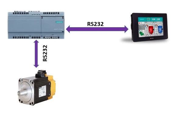
Legacy Systems: Many older systems and devices in various industries rely on RS232 for data exchange and control due to its compatibility and wide adoption.
Point-of-Sale (POS) Systems: RS232 is utilized in POS systems for connecting devices such as barcode scanners, cash registers, and receipt printers, ensuring seamless data transfer.

Telecommunications: RS232 finds use in telecommunications equipment like modems, routers, and switches, allowing configuration and management through a serial connection.

Medical Devices: RS232 is present in medical devices such as patient monitoring systems and diagnostic equipment, facilitating data transmission and control functionalities.
Embedded Systems: RS232 is popular in embedded systems and microcontroller-based projects, providing a simple means of programming and debugging.

How does the RS232 protocol work?
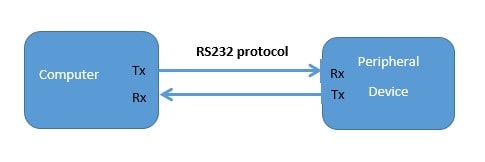
Consider a scenario where you have a computer (DTE – Data Terminal Equipment) connected to a modem (DCE – Data Communication Equipment) using an RS232 cable. The computer wants to send data to the modem for transmission over a telephone line.
The RTS (Ready to Send) signal is used by the Data Terminal Equipment (DTE) device, such as a computer, to inform the Data Communication Equipment (DCE) device, like a modem, that it is ready to transmit data. When the DTE is prepared to send data, it sets the RTS line to a logic high (1) level. The DCE receives this signal and acknowledges it by activating the Clear to Send (CTS) line.
The CTS (Clear to Send) signal is used by the DCE device to indicate that it is ready to receive data from the DTE device. When the DCE is prepared to receive data, it sets the CTS line to a logic high (1) level. The DTE receives this signal and can proceed with transmitting data.
The TXD (Transmit Data) line is used by the DTE to transmit data to the DCE. The DTE sends the binary data bits serially, one bit at a time, over the TXD line. The data is encoded and transmitted following the RS232 voltage levels and protocol.
For example: suppose we want to send 8 bits of information (11001110) to a computer (DTE) to a modem (DEC) then at first we make the RST of DTE to high. At this, DCE clears its CTS and informs DTA that DCE is ready to receive data from DTE. Sending data starts with a star bit that should be 0. After sending start bit data is transmitted by the TX line in this case the data is 11001110. A parity bit is sent after finishing to send data bits and it’s not mandatory to send. One or two bit of stop bit is sent to finish the transmission. Keep in mind that the stop bit should always be 1. Therefore, the total data packet will be 01100111011.

How RS232 protocol processes the data
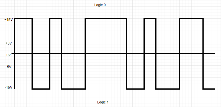
Voltage levels.
RS232 employs voltage levels to represent binary data. Traditionally, positive voltage represents logic 0 which ranges from +5V to +15V, while negative voltage represents logic 1 in the range of -5V to -15V. Logic 1 is referred to as “marking” and logic 0 is referred to as “spacing”. However, modern RS232 implementations often use inverted logic, where positive voltage represents logic 1, and negative voltage represents logic 0.
Data Encoding
To transmit data effectively, RS232 utilizes a method called data encoding. It converts the binary data into a format suitable for transmission over the serial connection. Commonly used encoding schemes include ASCII (American Standard Code for Information Interchange) and Unicode.
Start and Stop Bits
RS232 adds start and stop bits to each data byte transmitted. These bits provide synchronization and framing for the data. The start bit indicates the beginning of a data byte usually referred to as 0, while the stop bit marks its end. Typically, RS232 uses one start bit and one or two stop bits.
The parity bit is a basic error-checking mechanism used in data communication. It comes in four variations: even, odd, marked, and spaced. To illustrate, consider the number 011. In the case of even parity, the parity bit would be set to 0, while for odd parity, it would be set to 1.

The baud rate determines the speed at which data is transmitted over an RS232 connection. It represents the number of signal changes per second. Common baud rates for RS232 communication include 9600, 19200, and 115200 bits per second (bps). Higher baud rates allow for faster data transfer but may require more reliable cabling.
RS232 Cable
An RS232 cable, also known as a serial cable, is used to establish a connection between devices that follow the RS232 serial communication standard. This cable enables the transmission of data and control signals between devices such as computers, modems, printers, and other peripherals.
RS232 Connector Types
RS232 supports different connector types, including DB9 and DB25. The DB9 connector comprises nine pins, while the DB25 connector has 25 pins. These connectors ensure a secure and reliable physical connection between devices.
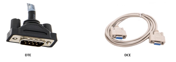
These cables are of two types one is Male connectors (DTE) and another one is female connectors (DCE). For example, DTE (Data transmission Equipment) cable is used for communicating between PC and modem, and DCE (Data communication Equipment) cable is used for communicating between modem and PLC or microcontroller.
DB-9 Connector
The DB9 connector, also known as a DE-9 connector, is a common type of serial communication port. It features nine pins arranged in a compact rectangular shape. The DB9 connector is widely used for various applications, including connecting peripherals such as mice, keyboards, and printers to computers, as well as for serial communication (RS232) between devices like modems, routers, and industrial equipment. You can buy it from Amazon
DB-9 Connector Connection Diagram
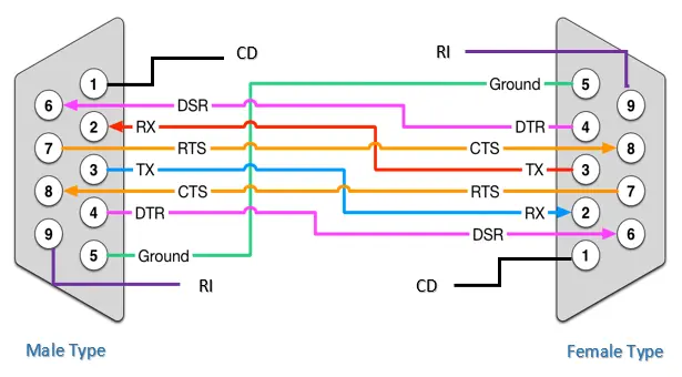
DB-9 Connector Pinout
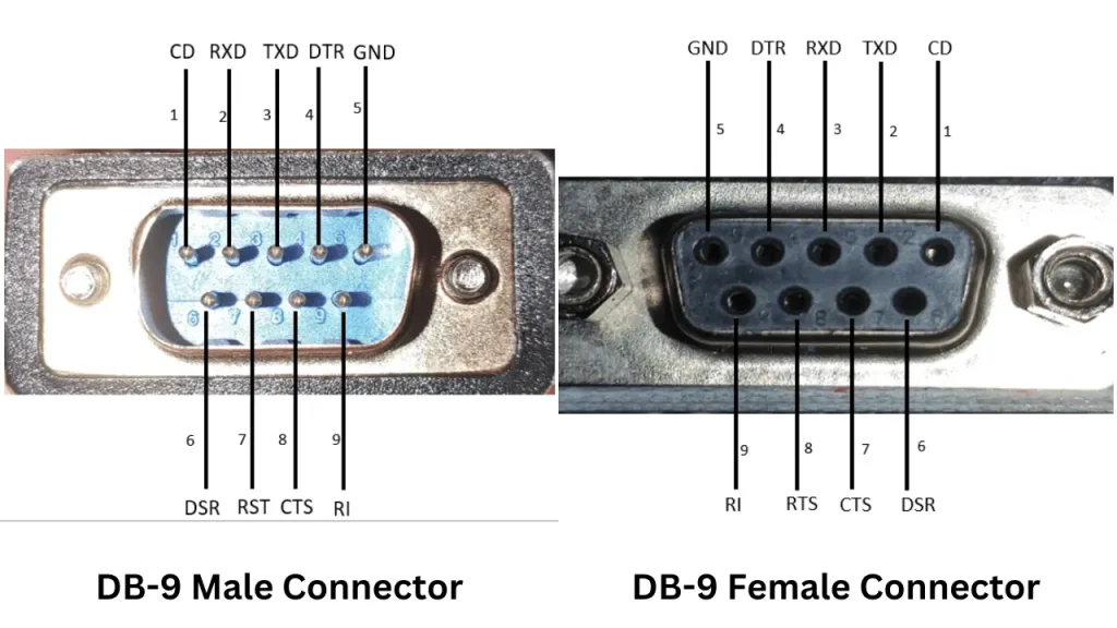
DB-9 connector pin definition
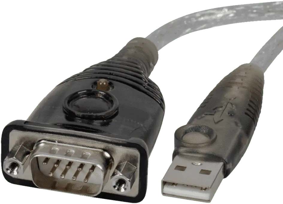
Rs232 to usb cable.
There are another three types of custom RS232 cables available in the market. The first one is RS232 to USB which helps you to communicate your PC to RS232 devices. This type of cable is also available in Amazon .
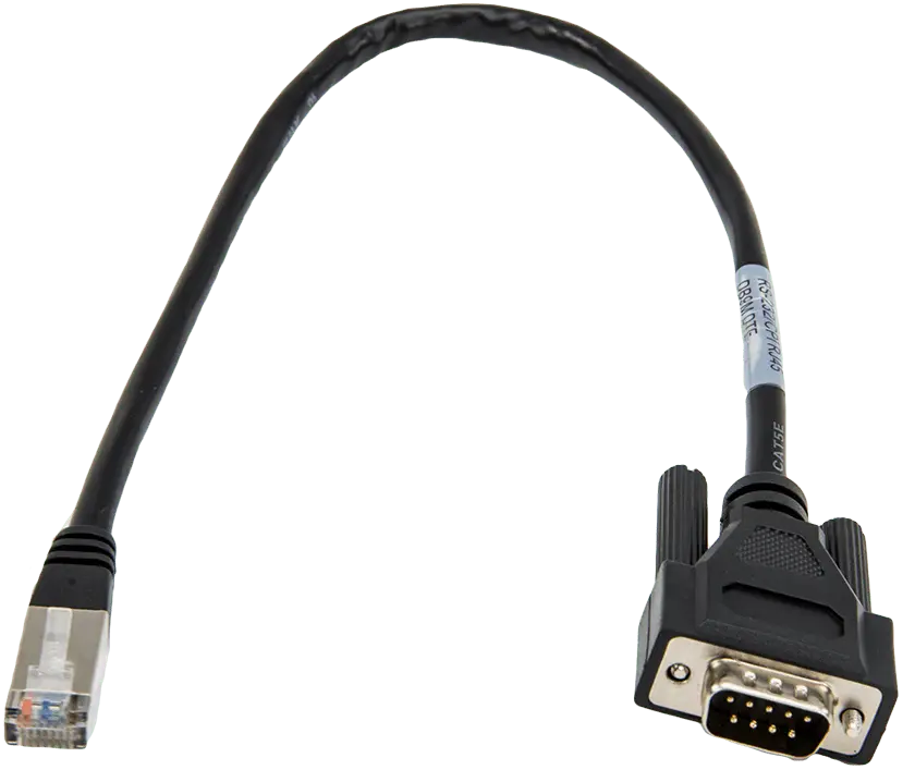
RS232 to Ethernet Cable
2 nd one is RS232 to Ethernet which also allows you to communicate your PC to RS232 devices. RS232 to Ethernet cable is also available in Amazon .
RS232 to UART module
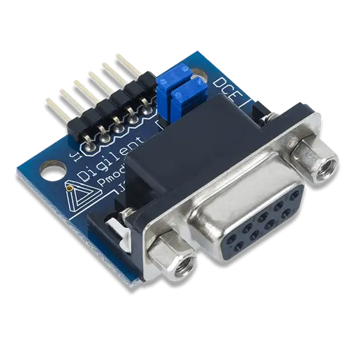
And 3rd one is a module for communicating between the microcontroller and PC using RS232 protocol. This module is DCE (Data Communication Equipment) module and to communicate with PC you need DTE (Data transmission Equipment) for example, DB9.
Cable Length Limitations
An important consideration in RS232 communication is the limitations imposed by cable length. Due to voltage drop and signal degradation, RS232 cables are typically limited to a maximum length of 50 feet (15 meters). However, the use of signal amplifiers or converters can extend the reach of RS232 communication.
Limitations of RS232 Protocol
While RS232 has been widely used for serial communication, it also has certain limitations that have led to its declining popularity in recent years. Here are some of the limitations of RS232:
Limited Transmission Distance: RS232 communication is limited in terms of transmission distance. Typically, the maximum reliable distance for RS232 is around 50 feet (15 meters). Beyond this distance, signal degradation can occur, leading to errors in data transmission. This limitation makes RS232 less suitable for long-distance communication requirements.
Lower Data Transfer Rates: RS232 is a relatively slower communication protocol compared to modern alternatives such as USB, Ethernet, or wireless technologies. It is typically limited to lower data transfer rates, typically ranging from 19.2 kbps (kilobits per second) to 115.2 kbps. This limitation can be restrictive for applications that require high-speed data transmission.
Incompatibility with Modern Interfaces: RS232 interfaces are not directly compatible with many modern devices such as smartphones, tablets, and laptops, which often lack RS232 ports. This incompatibility makes it challenging to connect RS232 devices directly to these newer devices without additional adapters or converters.
Bulkiness and Cable Limitations: RS232 cables, especially those with DB9 or DB25 connectors, can be bulky and less flexible compared to modern cable types. The size and limitations of RS232 cables can restrict their use in compact or portable devices where space is a constraint.
Lack of Plug-and-Play Support: RS232 communication typically requires manual configuration and setup of communication parameters such as baud rate, parity, and stop bits. This lack of plug-and-play support can make initial setup and troubleshoot more complex compared to newer communication interfaces that offer automatic detection and configuration.
Despite these limitations, RS232 still finds utility in specific applications, especially in legacy systems, industrial automation, and scenarios where compatibility with existing RS232 devices is crucial. However, for many modern applications, alternative communication protocols with higher data rates, longer transmission distances, and more convenient interfaces have become preferred choices over RS232.
Rana Bhuiyan
I hold a B.Sc degree in Electrical & Electronic Engineering from Daffodil International University, Bangladesh. I am an Electronic circuit designer and Microcontroller programmer. I am interested in Robotics, Embedded System Design and IoT.
Recent Posts
ESP32 Bluetooth Classic tutorial using Arduino IDE
The ESP32 Microcontroller is a versatile tool for IoT projects, combining WiFi and Bluetooth in a single chip. This post will guide you through interfacing Bluetooth Classic with ESP32 to establish...
How to Interface ESP32 with SIM7600 4G LTE Module using Arduino IDE
In a world of connectivity, the demand for faster, more reliable internet access is ever-growing. That's why IoT devices depend not only on WiFi or GSM (2G). 4G LTE communication has become popular...

Access denied under U.S. Export Administration Regulations.
RS-232: Serial Interface
Last Edited
RS-232 is a serial communication standard that, despite its age, still has a variety of uses in today’s digital landscape. This article dives into the intricacies of RS-232, starting with a basic understanding of what it is, followed by its pin assignments, V.24 and V.28 interfaces, and an explanation of the Null Modem concept. While it may seem like a relic of the past, RS-232 continues to find relevance in modern applications and is a fundamental topic for anyone invested in computer networking and communication systems.
What is RS-232?
More properly known as RS-232C, is a widely implemented serial transmission interface developed by the Electronic Industries Alliance ( EIA ) that is used for connecting data terminal equipment (DTE) such as computers or terminals to data communications equipment (DCE) such as modems, packet assembler/disassemblers (PADs), or serial printers. The RS-232 specification uses unbalanced lines to provide full-duplex serial communication using baseband transmission.
RS-232 provides a typical data rate of 19.2 Kbps over a maximum distance of 15 meters, but the maximum data transfer rate is 115.2 Kbps. Up to two devices can be connected using RS-232. Devices cannot be daisy-chained together using RS-232. (Use RS-422/423 instead.)
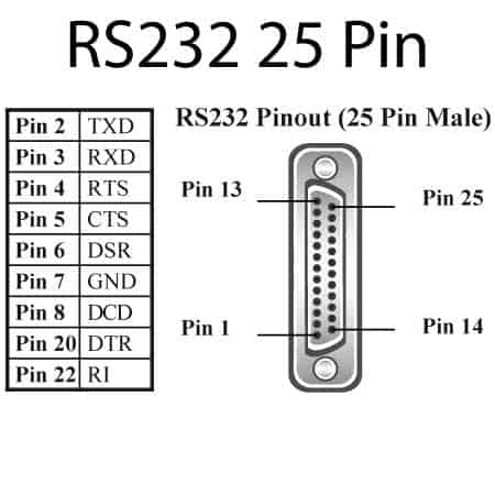
RS-232 specifies the types of wires and connectors, the pinning of the connectors and the function of each wire, the voltage levels and their meanings, and control procedures such as handshaking. RS-232 cables (cables designed to use the RS-232 serial interface specification) are typically 25-wire unshielded twisted-pair (UTP) cables with DB25 type connectors or 9-wire cables with DB9 connectors. The pin assignments are shown in the following table. Note that only pins 1 through 8 and pin 20 are required for most basic RS-232 functions, which means that 9-pin DB9 connectors can be used on RS-232 serial cables for most applications.
Pin Assignments of RS-232
In a PC, RS-232 is typically implemented in a universal asynchronous receiver-transmitter (UART) chip, which converts the internal parallel bus signal to a serial bit stream and vice versa, enabling communication between your system bus and serial devices .
RS-232 is compatible with the V.24 and V.28 standards from the International Telecommunication Union ( ITU ).
You can use RS-232 with a null modem cable to connect two pieces of DTE (for example, to transfer files). If you are having trouble with an RS-232 connection, be sure that you’re using a regular cable for DTE–DCE communication or a null modem cable for DTE–DTE communication – they look the same but are incompatible.
Although the maximum speed of RS-232 is 115.2 Kbps, older PCs support rates of up to only 56 or 64 Kbps. Newer PCs have a 16550 UART chip that supports serial throughput rates of up to 460.8 Kbps.
Historical Background of RS-232: The Bedrock of Serial Communication
The annals of computing and data communication are replete with transformative technologies that have fundamentally changed the way we exchange information. Among these technologies, one stands out for its enduring utility and adaptability: RS-232. To fully grasp its relevance, it’s essential to plunge into the narrative of its origin, its evolution, and its indefatigable relevance in an otherwise futuristic tech landscape.
The Genesis: A World Before Wireless
RS-232 was birthed into the world in 1960 by the Electronic Industries Association (EIA) , an epoch where wireless and USB communication systems were the stuff of science fiction. Initially dubbed as EIA RS-232, this standard was formulated to allow disparate pieces of hardware—think teletypewriters, modems, and eventually computers—to converse using a standardized protocol.
The ASCII Revolution
The emergence of the American Standard Code for Information Interchange (ASCII) in the early 1960s was a pivotal moment for RS-232. This character encoding standard brought a universal language that could be transmitted over RS-232 interfaces. Suddenly, an array of devices could not only connect but also “understand” each other, setting the stage for an interconnected computing environment.
Surviving the Age of Transformation
As computing power increased exponentially through the ’70s and ’80s, so did the demands for faster and more complex communication systems. Technologies like Ethernet and USB came into existence, promising higher data rates and more versatile functionalities. It would have been easy for RS-232 to fade into obsolescence, yet it clung on, proving its mettle in industrial, scientific, and even some consumer applications. The reason? Its simplicity, reliability, and a sprawling ecosystem of legacy systems that were ‘born’ speaking the RS-232 language.
The Modern Resurgence
Fast-forward to the 21st century; the world has largely moved to wireless technologies, fiber optics, and cloud-based solutions. Yet, walk into any manufacturing floor, aeronautical control system, or even some contemporary data centers, and you’ll still find RS-232 connectors and cables. The protocol has adapted itself to modernity, and you’ll find RS-232-to-USB converters, reaffirming the technology’s tenacious will to stay relevant.
» You should also read this article: Difference between RS-232 and USB .
The Evergreen Utility
Why does RS-232 continue to thrive? It comes down to a few crucial factors: ease of implementation, low operational costs, and a level of directness in point-to-point connections that still outpaces many flashy, modern alternatives in specific scenarios. As we venture into an era that embraces IoT and edge computing, RS-232 stands tall as a robust, tried-and-tested option for serial communication—demonstrating that age, in the world of technology, is but a number.
- RFC 1659 – Definitions of Managed Objects for RS-232-like Hardware Devices using SMIv2
RS-232: Connectors and Cabling
Most serial ports follow a standard called the RS-232 specification. RS-232 is a sort of "do all" specification, and as such is not perfect in every situation. In fact, it's overkill for most standard communication. However, it's good enough to have become an industry standard.
RS-232 defines the meaning of the different serial signals and their respective pin assignments on a standard 25-pin (DB-25) serial connector. Table 1 (a plain text version is also available) shows these assignments. Luckily, in standard types of communications only 9 of these pins are important: 1-8, and 20.
DB-25 connectors are either male, with the pins sticking out, or female, with matching holes. Often there are very small numbers marking the pins or holes 1-25. The female connector is a mirror image of the male so that pins and holes match.
Originally, there was no standardization of the gender of connectors and serial devices. Both connectors and serial devices could be either gender. However, since male connectors are more susceptible to injury than female, most expensive computing hardware these days has female connectors, while cables are male on both ends.
Since RS-232 defines signals that are not used for most standard communication, sometimes DB-25 connectors are missing unneeded pins. In this case, serial cables simply leave the unused pins disconnected.
There are two cable configurations in use today for serial equipment:
These different configurations determine which signal a device expects on which pin. All devices are configured as either DTE or DCE. Because terminals are typically DTE, and modems are typically DCE, you must use a different cable between a computer and a terminal than between a computer and a modem. We will talk more about this cabling difference later.
The RS-232 specification defines the the maximum length of serial cable to be 75 feet at 9,600 bps. This is a pretty conservative figure and has been stretched as far as 1,000 feet. How far the limit can be stretched depends on the brand of terminal and computer you are using. This is something to keep in mind when connecting terminals to computers in other rooms.
Alternate Serial Connectors
Because of the fact that RS-232 defines signals that go unused in standard types of communication, and because the traditional DB-25 connector is large an unwieldy (especially for small equipment, like laptops), many alternate serial connectors have come into widespread use. These connectors provide the same necessary pins as a DB-25, but are smaller, more manageable connectors. Because they provide access to the same signals, devices that use different connectors are compatible as long as you use the right kind of converter cable.
DIN-8 serial connectors are small, and almost circular. They are used on Macs, and often on laptops because they are so compact. DIN-8s provide the seven most common serial signals whose pin assignments are shown in Table 2 (a plain text version is also available).
DB-9s are most commonly found on PCs. They look like smaller versions of the DB-25 connector. DB-9s provide the eight most common serial signals whose pin assignments are shown in Table 3 (a plain text version is also available).
RJ-45 connectors look a lot like standard telephone connectors ... but they're not. They house eight wires instead of the four wires in a telephone connector. RJ-45s are not typically found on computers or normal serial equipment, but, because they are so small, they are often used on devices that have a lot of ports very close together. Terminal servers are a good example of devices that often use RJ-45 connectors.
There are many wiring schemes for mapping the pins on an RJ-45 connector to a DB-25 connector. Possibly the best is the Yost standard, which wires all RJ-45 to DB-25 connections the same way. The advantages this system provides are:
- All cable connections are of the same gender.
- There is no distinction between DTE and DCE.
- Because of the above, you can use the same kind of cable everywhere.
For more information about the Yost wiring standard see the optional document, Yost Serial Device Wiring Standard .
Hard Vs. Soft Carrier
When a serial device is attached to the system and turned on, Unix expects the DCD signal (data carrier detect) to be asserted. If your system pays close attention to whether that signal is asserted, you are using what is called hard carrier . Most systems also allow you to use soft carrier where the system pretends that the DCD signal is always asserted.
Soft carrier is often a very good thing for certain devices. For instance, with a terminal, it lets you use only 3 wires for a connection: transmitted data, received data, and signal ground. However, in a modem connection, you really want to pay attention to DCD. When you are connected via a modem, if the carrier signal is lost, you want the modem to hang up. If you are using soft carrier, DCD is assumed to be asserted, so even if you lose the signal, the modem can remain connected. This can be very bad news over a long distance connection since the modem could potentially remain connected for days.
Most modern systems set a default carrier mode for serial ports in their configuration files. The command stty -CLOCAL will force a terminal to use soft carrier, so for instance:
would enable soft carrier on serial port ttya.

What is RS232 Protocol and How it Works?
Historically, RS232 Communication protocol is an old serial communication protocol developed by EIA (Electronics Industry Alliance)/TIA (Telecommunications Industry Association)-232 in the year 1962. Modern hardware designs use innovative serial communication protocols like USB, Ethernet, and Wi-Fi. But still, RS232 has proven to be prominent. The reason is, RS232 signals spread over longer distances when compared to I2C and serial TTL signals. Moreover, it has better noise immunity. It is proven to be compatible across different manufacturers for interfacing computer and modems.
What is RS232 Protocol?
In RS232, ‘RS’ stands for Recommended Standard. It defines the serial communication using DTE and DCE signals. Here, DTE refers to Data Terminal Equipment and DCE refers to the Data Communication Equipment. Example of DTE device is a computer and DCE is a modem. Formally, it is specified as the interface between DTE equipment and DCE equipment using serial binary data exchange.
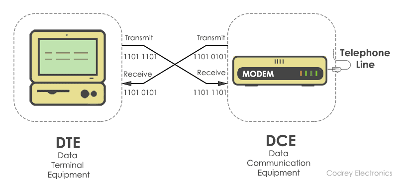
The DTE (computer) transmits the information serially to the other end equipment DCE (modem). In this case, DTE sends binary data “11011101” to DCE and DCE sends binary data “11010101” to the DTE device.
RS232 describes the common voltage levels, electrical standards, operation mode and number of bits to be transferred from DTE to DCE. This standard is used for transmission of information exchange over the telephone lines.
Electrical Standards
The electrical specifications for RS232 are updated in the year 1969. It specifies the electrical voltages, slew rate, line impedance, operation mode, and baud rate.
Voltage Levels
The line voltages of RS232 range from -25V to +25V. They are categorized as signal voltage and control voltage.

The signal voltage between +3V to +25V represents logic ‘1’ and the signal voltages between -3V to -25V represents logic ‘0’. Whereas the control voltage signals use negative logic, i.e., logic ‘1’ indicates -3 to -25 volts and logic ‘0’ indicates +3V to +25V. The voltage from -3V to +3V is considered as an indeterminate state.
The change of input voltage determines the rate at which the RS232 driver responds. This is often termed as slew rate. The RS232 standard maintains a minimum slew rate with slow rise and fall time to reduce the cross-talk between neighbouring signals. Normally, the maximum slew rate allowed is 30V/µsec.
Line Impedance
The impedance bridging between RS232 driver and the receiver is defined to maximize the voltage transfer between the transmitter and receiver. It is in the range of 3KΩ to 7KΩ.
Mode of Operation
The RS232 devices work on single-ended signaling (two wire). This means one wire transmits an altering voltage and another wire is connected to ground. Single-ended signals are affected by the noise induced by differences in ground voltages of the driver and receiver circuits. The advantage of the single-ended technique is, it requires fewer wires to transmit information.
It is the number of binary bits transferred per second. RS232 supports baud rates from 110 to 230400. Commonly, the baud rate with 1200, 4800, 9600, 115200 are used. It determines the speed at which data is to be sent from the transmitter to the receiver.
Note: The baud rate has to be same at both the transmitter side and receiver side.
Communication Interface
RS232 determines the communication between the DTE and DCE using DB9 and DB25 connectors. The D-sub connectors (DB9, DB25) comes with male and female cable. DB9 connector has 9 pins and DB25 connector has 25 pins with each pin having its own function.
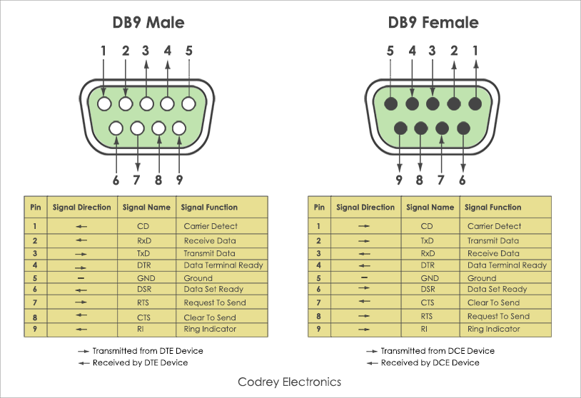
Functional Description
Apart from the electrical characteristics, RS232 defined the functions of signals that are used in the serial interface. Some of them are common ground, Data, control and timing signals. Here is a list of signals used in RS232 pinout.
Other than above signals, (primary signals) RS232 provides secondary signals such as secondary DTE, secondary RTS, secondary DCD, secondary TxD and secondary RxD for optional connection of DTE and DCE.
Types of Serial Cables
To make serial communication possible between DTE and DCE, two types of RS232 cables exist. They are Null modem and Straight-cable. In null modem cable , the TX (Transmitter) pin of the male connector is linked up with the RX (Receiver) pin of the female and the RX pin of the male is connected to TX pin of the female.
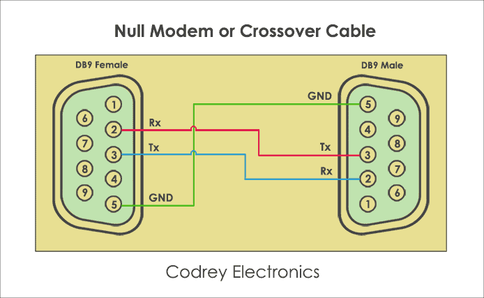
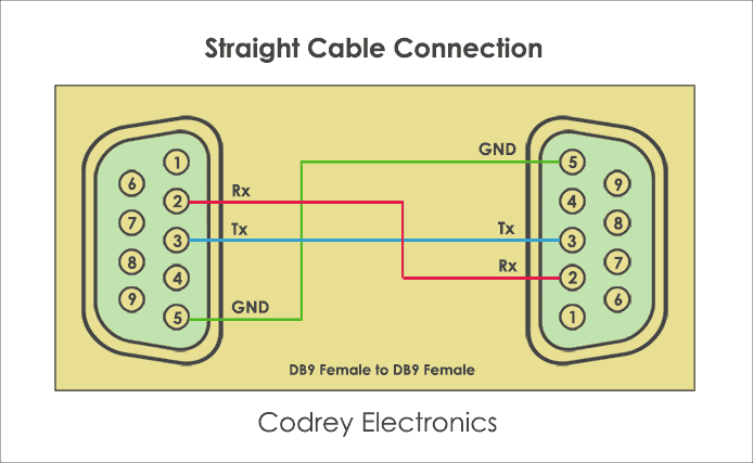
Next one, is the Straight-through cable . As the name implies, it is a one to one connector, i.e. a transmit pin of one device is connected to transmit pin of another device and receiver pin of one device is connected to receiver pin of another device. Apart from connections, the cable length depends upon the wiring capacitance. As per specification, the cable length is nearly 80 feet.
How RS232 Communication Works?
The working of RS-232 can be understood by the protocol format. As RS-232 is a point-to-point asynchronous communication protocol, it sends data in a single direction. Here, no clock is required for synchronizing the transmitter and receiver. The data format is initiated with a start bit followed by 7-bit binary data, parity bit and stop bit which are sent one after another.

Protocol Format
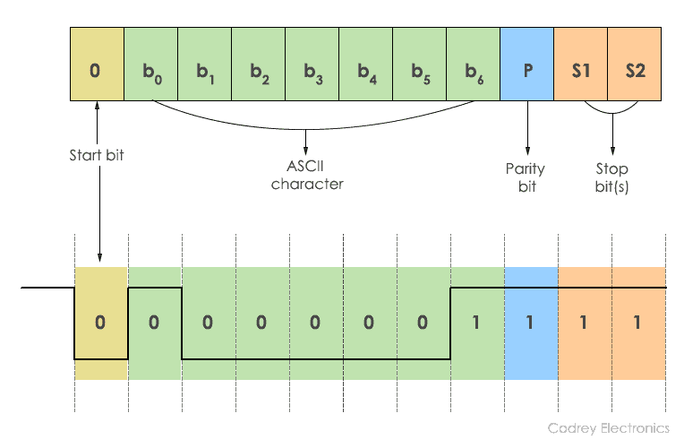
The transmission begins by sending a Start bit ‘0’. This is succeeded by 7 bits of ASCII data. The parity bit is appended to this data for the receiver validation. The data sent from the transmitter should match at the receiver. Finally, the transmission is halted using a stop bit and it is represented by the binary ‘1’. Generally, 1 or 2 stop bits can be sent.
In the above diagram, ASCII character ‘A’ is sent using a serial binary stream of ‘1’s and ‘0’s. While sending data, there should be a certain delay between each bit. This delay is considered as inactive time and the RS232 line is at negative logic state (-12V).
What is Handshaking?
Handshaking is the process of interchanging information signals between the sender (transmitter) and receiver. These signals build a communication link between the transmitter and receiver. In RS232, there are two types of handshaking. They are hardware handshaking and software handshaking.
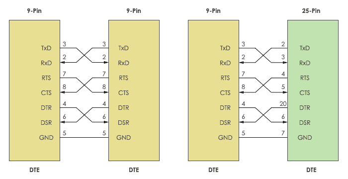
The connectors DB9 and Db25 are used for handshaking purpose. When no handshaking is performed, only the TxD (Transmitter) and RxD are cross-coupled. Other pins, RTS, CTS, DSR, and DTR are connected in loopback fashion.
To use the handshaking technique, RTS and CTS are cross-coupled. Also, DTR and DSR are also connected in cross mode.
Why to use Handshaking?
To send and receive the information without loss of data, it is necessary to maintain robust communication between the transmitter and receiver. To do that, buffer is used. Buffer is a temporary storage location which allows the transmitter and receiver to store the data until the information is processed by each other at different speeds.
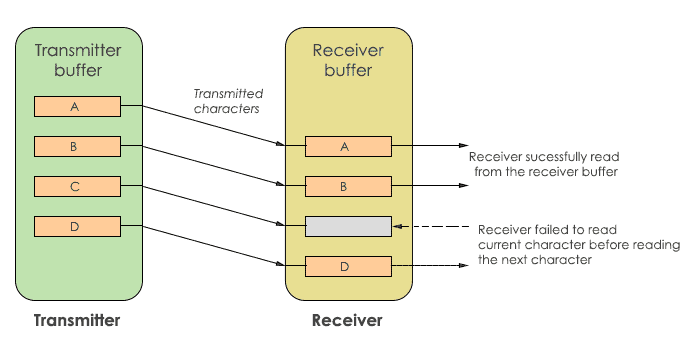
In the above diagram, the transmitter and receiver have their own buffer. The transmit buffer holds the characters to be sent to the receiver. While the receive buffer holds the characters received from the transmitter. If the transmitter sends data at a higher speed, the receiver may fail to receive. In this case, character ‘C’ is missed by the receiver. To avoid this, handshaking is used. Handshaking allows the transmitter and receiver device to agree before the communication is going to start.
Hardware Handshaking
The flow control of data transmission and reception is done using hardware handshaking . It uses control signals DTR, DSR, RTS and CTS signals. Typically, when establishing communication between a computer and modem RTS and CTS signals are used.
It stops the data being replaced in the receiver buffer. The signals are kept in a high state (logic ‘1’) to activate handshaking.
Software Handshaking
This type of handshaking uses two ASCII characters for start-stop communication. Hence, this is known as software flow control. Software handshaking use XON/XOFF character to control the serial communication. ‘XON’ represents Ctrl+S or ASCII character 11, whereas ‘XOFF’ represents Ctrl+Q or ASCII 13. This handshaking requires 3 wires. They are TXD, RXD and signal GND.
When ‘XOFF’ character is enabled, the communication is closed until ‘XON’ character is received by the transmitter. In some cases, the receiver buffer may overload which causes the receiver to send ‘XOFF’ automatically to the transmitter.
How Handshaking Works?
In the initial state, the RTS line is pulled high by the DTE to wake up the DCE. In this state no data is transmitted. After that, DCE puts the CTS line HIGH to receive the data. This makes the DTE to respond and set the DTR into the HIGH state. Now, the data transfer takes place. After completion of data transfer, both RTS and DTR are pulled LOW by DTE. Then, DCE triggers the CTS line to the LOW state. This stops the DTE to transmit the data.
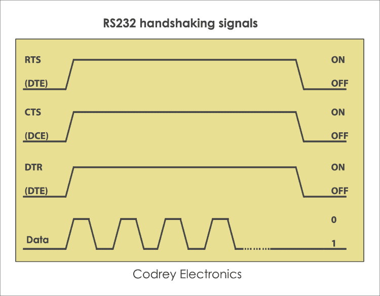
In this way, handshaking takes place by DTE request, taking control of the communication link and lets the DCE transfer data.
Difference between RS232 and UART
The main difference between RS232 and UART protocol is the voltage levels. Apart from this, they both supports half duplex and full duplex communication.
Microcontrollers don’t tolerate RS232 voltages and may be damaged. To avoid this, UART (Universal Asynchronous Transmitter Receiver) is used. It sends and receives the data in serial form. To do the level conversion of voltages, RS232 driver IC such as MAX232 is used between the UART and serial port.
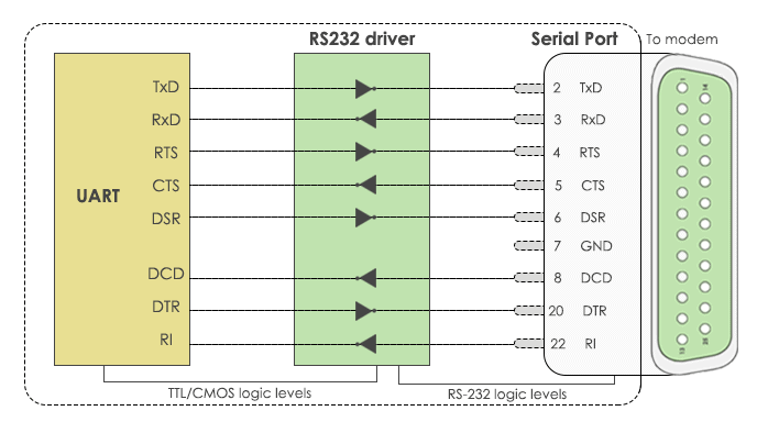
The advantages of RS232 make it as a standard serial interface for system to system communication and also for the following benefits.
- Simple protocol design.
- Hardware overhead is lesser than parallel communication.
- Recommended standard for short distance applications.
- Compatible with DTE and DCE communication.
- Low cost protocol for development.
Disadvantages
The limitations of RS232 protocol are, it doesn’t support full-duplex communication and it is a single-ended protocol which shifts the ground potential. Moreover, the longer cable length introduces cross talk during serial communication . Hence, this protocol is restricted for long distance communication.
Applications
RS232 communication is used in different applications. Some of them are:
- Teletypewriter devices.
- Demodulator applications.
- PC COM port interfacing.
- In embedded systems for debugging.
- Modems and printers.
- Handheld equipment.
- CNC controllers, Software debuggers etc.
- Barcode scanners and Point of Sales (POS) terminals.
Related Posts
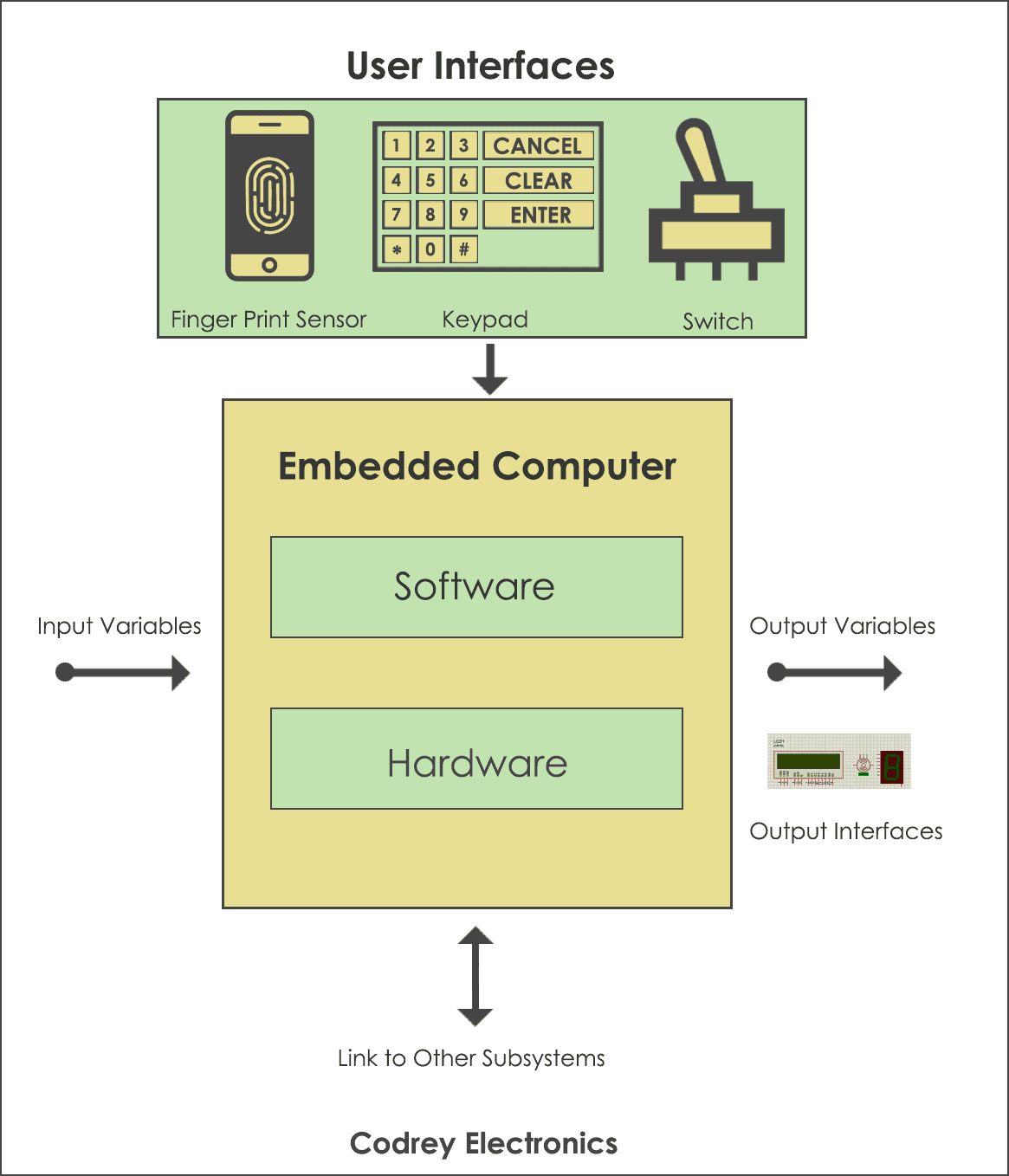
What is Embedded System and How it Works?
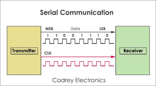
What is Serial Communication and How it works?

Career in Embedded Systems: Worldwide Opportunities
Very clear and helpful article – one observation/question …
The diagram showing DTE and DCE connectors ( https://www.codrey.com/wp-content/uploads/2017/09/DB9-Male-and-Female-Pinouts.png ) seems to contradict itself … eg “Receive Data” is shown as pin #2 on the male connector (left side diagram) but the direction of the arrow underneath indicates “Transmitted from DTE device”
conversely, “Transmit Data” is shown as pin #3 on the male connector (left side diagram) but the direction of the arrow underneath indicates “Received by DTE device”
could you clarify. Many thanks
Hi Neil, Thanks for the correction. In this case, The male connector acting as DTE device transmits the data hence the direction ( –> ) and female connector acting as DCE device receives the data. hence the direction ( <---). This may vary in special cases, the male connector may be designed as DCE and female connector as DTE. Hope it helps.
Good detail explanation
Leave a Reply Cancel reply
Your email address will not be published. Required fields are marked *
Help Center Help Center
- Help Center
- Trial Software
- Product Updates
- Documentation
Serial Port Overview
What is serial communication.
Serial communication is the most common low-level protocol for communicating between two or more devices. Normally, one device is a computer, while the other device can be a modem, a printer, another computer, or a scientific instrument such as an oscilloscope or a function generator.
As the name suggests, the serial port sends and receives bytes of information in a serial fashion—one bit at a time. These bytes are transmitted using either a binary format or a text (ASCII) format.
For many serial port applications, you can communicate with your instrument without detailed knowledge of how the serial port works. Communication is established through a serial port object, which you create in the MATLAB ® workspace.
If your application is straightforward, or if you are already familiar with the topics mentioned above, you might want to begin with Create Serial Port Object . If you want a high-level description of all the steps you are likely to take when communicating with your instrument, refer to Get Started with Instrument Control Toolbox .
Serial Port Interface Standard
Over the years, several serial port interface standards for connecting computers to peripheral devices have been developed. These standards include RS-232, RS-422, and RS-485 — all of which are supported by the serialport object. The most widely used standard is RS-232.
The current version of this standard is designated TIA/EIA-232C, which is published by the Telecommunications Industry Association. However, the term “RS-232” is still in popular use, and is used here to refer to a serial communication port that follows the TIA/EIA-232 standard. RS-232 defines these serial port characteristics:
Maximum bit transfer rate and cable length
Names, electrical characteristics, and functions of signals
Mechanical connections and pin assignments
Primary communication uses three pins: the Transmit Data pin, the Receive Data pin, and the Ground pin. Other pins are available for data flow control, but are not required.
This guide assumes that you are using the RS-232 standard. Refer to your device documentation to see which interface standard you can use.
Supported Platforms
The MATLAB serial port interface is supported on:
Linux ® 64-bit
macOS 64-bit
Microsoft ® Windows ® 64-bit
RS-232 is not supported on macOS 13 or later.
Connecting Two Devices with a Serial Cable
The RS-232 and RS-485 standard defines the two devices connected with a serial cable as the data terminal equipment (DTE) and data circuit-terminating equipment (DCE). This terminology reflects the RS-232 origin as a standard for communication between a computer terminal and a modem.
In this guide, your computer is considered a DTE, while peripheral devices such as modems and printers are considered DCEs. Note that many scientific instruments function as DTEs.
Because RS-232 mainly involves connecting a DTE to a DCE, the pin assignment definitions specify straight-through cabling, where pin 1 is connected to pin 1, pin 2 is connected to pin 2, and so on. A DTE-to-DCE serial connection using the transmit data (TD) pin and the receive data (RD) pin is shown below. Refer to Serial Port Signals and Pin Assignments for more information about serial port pins.
If you connect two DTEs or two DCEs using a straight serial cable, then the TD pin on each device is connected to the other, and the RD pin on each device is connected to the other. Therefore, to connect two like devices, you must use a null modem cable. As shown below, null modem cables cross the transmit and receive lines in the cable.
You can connect multiple RS-422 or RS-485 devices to a serial port. If you have an RS-232/RS-485 adaptor, then you can use the serialport object with these devices.
Serial Port Signals and Pin Assignments
Serial ports consist of two signal types: data signals and control signals . To support these signal types, as well as the signal ground, the RS-232 standard defines a 25-pin connection. However, most PCs and UNIX ® platforms use a 9-pin connection. In fact, only three pins are required for serial port communications: one for receiving data, one for transmitting data, and one for the signal ground.
The following figure shows a pin assignment scheme for a nine-pin male connector on a DTE.
This table describes the pins and signals associated with the nine-pin connector. Refer to the RS-232 or the RS-485 standard for a description of the signals and pin assignments for a 25-pin connector.
Serial Port Pin and Signal Assignments
The term “data set” is synonymous with “modem” or “device,” while the term “data terminal” is synonymous with “computer.”
The serial port pin and signal assignments are with respect to the DTE. For example, data is transmitted from the TD pin of the DTE to the RD pin of the DCE.
Signal States
Signals can be in either an active state or an inactive state . An active state corresponds to the binary value 1, while an inactive state corresponds to the binary value 0. An active signal state is often described as logic 1 , on , true , or a mark . An inactive signal state is often described as logic 0 , off , false , or a space .
For data signals, the “on” state occurs when the received signal voltage is more negative than –3 volts, while the “off” state occurs for voltages more positive than 3 volts. For control signals, the “on” state occurs when the received signal voltage is more positive than 3 volts, while the “off” state occurs for voltages more negative than –3 volts. The voltage between –3 volts and +3 volts is considered a transition region, and the signal state is undefined.
To bring the signal to the “on” state, the controlling device unasserts (or lowers ) the value for data pins and asserts (or raises ) the value for control pins. Conversely, to bring the signal to the “off” state, the controlling device asserts the value for data pins and unasserts the value for control pins.
The following figure depicts the “on” and “off” states for a data signal and for a control signal.
Most serial port devices support full-duplex communication, meaning that they can send and receive data at the same time. Therefore, separate pins are used for transmitting and receiving data. For these devices, the TD, RD, and GND pins are used. However, some types of serial port devices support only one-way or half-duplex communications. For these devices, only the TD and GND pins are used. This guide assumes that a full-duplex serial port is connected to your device.
The TD pin carries data transmitted by a DTE to a DCE. The RD pin carries data that is received by a DTE from a DCE.
Control Pins
The control pins of a nine-pin serial port are used to determine the presence of connected devices and control the flow of data. The control pins include:
RTS and CTS Pins
DTR and DSR Pins
CD and RI Pins
RTS and CTS Pins. The RTS and CTS pins are used to signal whether the devices are ready to send or receive data. This type of data flow control — called hardware handshaking — is used to prevent data loss during transmission. When enabled for both the DTE and DCE, hardware handshaking using RTS and CTS follows these steps:
The DTE asserts the RTS pin to instruct the DCE that it is ready to receive data.
The DCE asserts the CTS pin, indicating that it is clear to send data over the TD pin. If data can no longer be sent, the CTS pin is unasserted.
The data is transmitted to the DTE over the TD pin. If data can no longer be accepted, the RTS pin is unasserted by the DTE and the data transmission is stopped.
To enable hardware handshaking, refer to Controlling the Flow of Data: Handshaking .
DTR and DSR Pins. Many devices use the DSR and DTR pins to signal if they are connected and powered. Signaling the presence of connected devices using DTR and DSR follows these steps:
The DTE asserts the DTR pin to request that the DCE connect to the communication line.
The DCE asserts the DSR pin to indicate that it is connected.
DCE unasserts the DSR pin when it is disconnected from the communication line.
The DTR and DSR pins were originally designed to provide an alternative method of hardware handshaking. However, the RTS and CTS pins are usually used in this way, and not the DSR and DTR pins. Refer to your device documentation to determine its specific pin behavior.
CD and RI Pins. The CD and RI pins are typically used to indicate the presence of certain signals during modem-modem connections.
CD is used by a modem to signal that it has made a connection with another modem, or has detected a carrier tone. CD is asserted when the DCE is receiving a signal of a suitable frequency. CD is unasserted if the DCE is not receiving a suitable signal.
RI is used to indicate the presence of an audible ringing signal. RI is asserted when the DCE is receiving a ringing signal. RI is unasserted when the DCE is not receiving a ringing signal (for example, it is between rings).
Serial Data Format
The serial data format includes one start bit, between five and eight data bits, and one stop bit. A parity bit and an additional stop bit might be included in the format as well. This diagram illustrates the serial data format.
The format for serial port data is often expressed using the following notation:
number of data bits - parity type - number of stop bits
For example, 8-N-1 is interpreted as eight data bits, no parity bit, and one stop bit, while 7-E-2 is interpreted as seven data bits, even parity, and two stop bits.
The data bits are often referred to as a character because these bits usually represent an ASCII character. The remaining bits are called framing bits because they frame the data bits.
Bytes Versus Values
The collection of bits that compose the serial data format is called a byte . At first, this term might seem inaccurate because a byte is 8 bits and the serial data format can range between 7 bits and 12 bits. However, when serial data is stored on your computer, the framing bits are stripped away, and only the data bits are retained. Moreover, eight data bits are always used regardless of the number of data bits specified for transmission, with the unused bits assigned a value of 0.
When reading or writing data, you might need to specify a value , which can consist of one or more bytes. For example, if you read one value from a device using the int32 format, then that value consists of four bytes. For more information about reading and writing values, refer to Write and Read Serial Port Data .
Synchronous and Asynchronous Communication
The RS-232 and the RS-485 standards support two types of communication protocols: synchronous and asynchronous.
Using the synchronous protocol, all transmitted bits are synchronized to a common clock signal. The two devices initially synchronize themselves to each other, and then continually send characters to stay synchronized. Even when actual data is not really being sent, a constant flow of bits allows each device to know where the other is at any given time. That is, each bit that is sent is either actual data or an idle character. Synchronous communications allows faster data transfer rates than asynchronous methods, because additional bits to mark the beginning and end of each data byte are not required.
Using the asynchronous protocol, each device uses its own internal clock, resulting in bytes that are transferred at arbitrary times. So, instead of using time as a way to synchronize the bits, the data format is used.
In particular, the data transmission is synchronized using the start bit of the word, while one or more stop bits indicate the end of the word. The requirement to send these additional bits causes asynchronous communications to be slightly slower than synchronous. However, it has the advantage that the processor does not have to deal with the additional idle characters. Most serial ports operate asynchronously.
In this guide, the terms “synchronous” and “asynchronous” refer to whether read or write operations block access to the MATLAB Command Window.
How Are the Bits Transmitted?
By definition, serial data is transmitted one bit at a time. The order in which the bits are transmitted follows these steps:
The start bit is transmitted with a value of 0.
The data bits are transmitted. The first data bit corresponds to the least significant bit (LSB), while the last data bit corresponds to the most significant bit (MSB).
The parity bit (if defined) is transmitted.
One or two stop bits are transmitted, each with a value of 1.
The number of bits transferred per second is given by the baud rate . The transferred bits include the start bit, the data bits, the parity bit (if defined), and the stop bits.
Start and Stop Bits
As described in Synchronous and Asynchronous Communication , most serial ports operate asynchronously. This means that the transmitted byte must be identified by start and stop bits. The start bit indicates when the data byte is about to begin and the stop bit indicates when the data byte has been transferred. The process of identifying bytes with the serial data format follows these steps:
When a serial port pin is idle (not transmitting data), then it is in an “on” state.
When data is about to be transmitted, the serial port pin switches to an “off” state due to the start bit.
The serial port pin switches back to an “on” state due to the stop bit(s). This indicates the end of the byte.
The data bits transferred through a serial port can represent device commands, sensor readings, error messages, and so on. The data can be transferred as either binary data or as text (ASCII) data.
Most serial ports use between five and eight data bits. Binary data is typically transmitted as eight bits. Text-based data is transmitted as either seven bits or eight bits. If the data is based on the ASCII character set, then a minimum of seven bits is required because there are 2 7 or 128 distinct characters. If an eighth bit is used, it must have a value of 0. If the data is based on the extended ASCII character set, then eight bits must be used because there are 2 8 or 256 distinct characters.
The parity bit provides simple error (parity) checking for the transmitted data. This table describes the types of parity checking.
Parity Types
Mark and space parity checking are seldom used because they offer minimal error detection. You can choose not to use parity checking at all.
The parity checking process follows these steps:
The transmitting device sets the parity bit to 0 or to 1 depending on the data bit values and the type of parity checking selected.
The receiving device checks if the parity bit is consistent with the transmitted data. If it is, then the data bits are accepted. If it is not, then an error is returned.
Parity checking can detect only one-bit errors. Multiple-bit errors can appear as valid data.
For example, suppose the data bits 01110001 are transmitted to your computer. If even parity is selected, then the parity bit is set to 0 by the transmitting device to produce an even number of 1s. If odd parity is selected, then the parity bit is set to 1 by the transmitting device to produce an odd number of 1s.
Find Serial Port Information for Your Platform
You can find serial port information using the resources provided by Windows, macOS , and UNIX platforms.
Your operating system provides default values for all serial port settings. However, these settings are overridden by your MATLAB code, and have no effect on your serial port application.
You can also use the instrhwinfo function to return the available serial ports programmatically.
Use the serialportlist Function to Find Available Ports
The serialportlist function returns a list of all serial ports on a system, including virtual serial ports provided by USB-to-serial devices and Bluetooth Serial Port Profile devices. The function provides a list of the serial ports that you have access to on your computer and can use for serial port communication. For example:
The serialportlist function shows both available and in-use ports on Windows and macOS systems, but on Linux, it shows only available ports and not in-use ports.
Windows Platform
You can access serial port information through the Device Manager .
Open Device Manager .
Expand the Ports (COM & LPT) list.

Double-click the Communications Port (COM1) item.
Select the Port Settings tab.

macOS Platform
For macOS machines, use the System Profiler to make sure that your device appears as a serial connection. If it is not present in System Profiler, serialportlist will not display it either.
UNIX Platform
To find serial port information for UNIX platforms, you need to know the serial port names. These names can vary between different operating systems.
On Linux, serial port devices are typically named ttyS0 , ttyS1 , and so on. You can use the setserial command to display or configure serial port information. For example, to display which serial ports are available:
To display detailed information about ttyS0 :
If the setserial -ag command does not work, make sure that you have read and write permission for the port.
For all supported UNIX platforms, including macOS , you can use the stty command to display or configure serial port information. For example, to display serial port properties for ttyS0 , type:
To configure the baud rate as 4800 bits per second, type:
This example shows how to set tty parameters, not the baud rate. To set the baud rate using the MATLAB serial interface, refer to Configure Serial Port Communication Settings .
MATLAB Command
You clicked a link that corresponds to this MATLAB command:
Run the command by entering it in the MATLAB Command Window. Web browsers do not support MATLAB commands.
Select a Web Site
Choose a web site to get translated content where available and see local events and offers. Based on your location, we recommend that you select: .
- Switzerland (English)
- Switzerland (Deutsch)
- Switzerland (Français)
- 中国 (English)
You can also select a web site from the following list:
How to Get Best Site Performance
Select the China site (in Chinese or English) for best site performance. Other MathWorks country sites are not optimized for visits from your location.
- América Latina (Español)
- Canada (English)
- United States (English)
- Belgium (English)
- Denmark (English)
- Deutschland (Deutsch)
- España (Español)
- Finland (English)
- France (Français)
- Ireland (English)
- Italia (Italiano)
- Luxembourg (English)
- Netherlands (English)
- Norway (English)
- Österreich (Deutsch)
- Portugal (English)
- Sweden (English)
- United Kingdom (English)
Asia Pacific
- Australia (English)
- India (English)
- New Zealand (English)
Contact your local office
The RS232 STANDARD
(renamed the "EIA232 Standard" in the early 1990's) Copyright © 1993-2015 by CAMI Research Inc., Acton, Massachusetts
Contents What is EIA232? Likely Problems when Using an EIA232 Interface Pin Assignments Cable Wiring Examples (New!) Signal Definitions Signal Ground and Shield Primary Communications Channel Secondary Communications Channel Modem Status and Control Signals Transmitter and Receiver Timing Signals Channel Test Signals Electrical Standards Common Signal Ground Signal Characteristics Signal Timing Accepted Simplifications of the Standard Pin Description Index References to EIA Publications Back to CableEye® Home Page
1 - The absence or misconnection of flow control (handshaking) signals, resulting in buffer overflow or communications lock-up. 2 - Incorrect communications function (DTE versus DCE) for the cable in use, resulting in the reversal of the Transmit and Receive data lines as well as one or more handshaking lines. 3 - Incorrect connector gender or pin configuration, preventing cable connectors from mating properly.
Fortunately, EIA232 driver circuitry is highly tolerant of misconnections, and will usually survive a drive signal being connected to ground, or two drive signals connected to each other. In any case, if the serial interface between two devices is not operating correctly, disconnect the cable joining this equipment until the problem is isolated.
Go to DTE Pinout (looking into the computer's serial connector) Go to DCE Pinout (looking into the modem's serial connector)
If the full EIA232 standard is implemented as defined, the equipment at the far end of the connection is named the DTE device (Data Terminal Equipment, usually a computer or terminal), has a male DB25 connector, and utilizes 22 of the 25 available pins for signals or ground. Equipment at the near end of the connection (the telephone line interface) is named the DCE device (Data Circuit-terminating Equipment, usually a modem), has a female DB25 connector, and utilizes the same 22 available pins for signals and ground. The cable linking DTE and DCE devices is a parallel straight-through cable with no cross-overs or self-connects in the connector hoods. If all devices exactly followed this standard, all cables would be identical, and there would be no chance that an incorrectly wired cable could be used. This drawing shows the orientation and connector types for DTE and DCE devices:
EIA232 communication function and connector types for a personal computer and modem. DCE devices are sometimes called "Data Communications Equipment" instead of Data Circuit-terminating Equipment.
Copyright © 1993-2002 CAMI Research Inc.
Copyright © 1993-2003 cami research inc..
IMPORTANT: Signal names that imply a direction, such as Transmit Data and Receive Data, are named from the point of view of the DTE device. If the EIA232 standard were strictly followed, these signals would have the same name for the same pin number on the DCE side as well. Unfortunately, this is not done in practice by most engineers, probably because no one can keep straight which side is DTE and which is DCE. As a result, direction-sensitive signal names are changed at the DCE side to reflect their drive direction at DCE. The following list gives the conventional usage of signal names:
The following wiring diagrams come from actual cables scanned by the CableEye® PC-Based Cable Test System. CableEye software automatically draws schematics whenever it tests a cable. Click here to learn more about CableEye.
1 - DB9 All-Line Direct Extension Next Cable | (no previous cable) || Next Topic This shows a 9-pin DTE-to-DCE serial cable that would result if the EIA232 standard were strictly followed. All 9 pins plus shield are directly extended from DB9 Female to DB9 Male. There are no crossovers or self-connects present. Use this cable to connect modems, printers, or any device that uses a DB9 connector to a PC's serial port. This cable may also serve as an extension cable to increase the distance between a computer and serial device. Caution: do not exceed 25 feet separation between devices without a signal booster! 80K Left Side: Connect to DTE (computer) Right Side: Connect to DCE (modem or other serial device) Cable image created by CableEye® 2 - DB9 Loopback Connector Next Cable | Previous Cable || Next Topic A loopback connector usually consists of a connector without a cable and includes internal wiring to reroute signals back to the sender. This DB9 female connector would attach to a DTE device such as a personal computer. When the computer receives data, it will not know whether the signals it receives come from a remote DCE device set to echo characters, or from a loopback connector. Use loopback connectors to confirm proper operation of the computer's serial port. Once confirmed, insert the serial cable you plan to use and attach the loopback to the end of the serial cable to verify the cable. In this case, Transmit Data joins to Received Data, Request-to-Send joins to Clear-to-Send, and DTE-Ready joins to DCE-Ready and Received Line Signal Detect. 80K Left Side: Connect to DTE (computer) Right Side: (none) Cable image created by CableEye® 3 - DB9 Null Modem Cable Next Cable | Previous Cable || Next Topic Use this female-to-female cable in any application where you wish to connect two DTE devices (for example, two computers). A male-to-male equivalent of this cable would be used to connect two DCE devices. The cable shown below is intended for RS232 asynchronous communications (most PC-based systems). If you are using synchronous communications, the null modem will have additional connections for timing signals, and a DB25 connector would be necessary. NOTE: Not all null modem cables connect handshaking lines the same way. In this cable, Request-to-Send (RTS, pin 7) asserts the Carrier Detect (pin 1) on the same side and the Clear-to-Send (CTS, pin 8) on the other side of the cable. This device may also be available in the form of an adapter. 80K Left Side: Connect to 9-pin DTE (computer) Right Side: Connect to 9-pin DTE (computer) Cable image created by CableEye® 4 - DB25 to DB9 Adapter Next Cable | Previous Cable || Next Topic Signals on the DB25 DTE side are directly mapped to the DB9 assignments for a DTE device. Use this to adapt a 25-pin COM connector on the back of a computer to mate with a 9-pin serial DCE device, such as a 9-pin serial mouse or modem. This adapter may also be in the form of a cable. 80K Left Side: Connect to 25-pin DTE (computer) Right Side: Connect to 9-pin DCE (modem) Cable image created by CableEye® 5 - DB25 to DB9 Adapter (pin 1 connected to shield) Next Cable | Previous Cable || Next Topic This adapter has the same wiring as the previous cable (#4) except that pin 1 is wired to the connector shell (shield). Note that the cable's shield is usually a foil blanket surrounding all conductors running the length of the cable and joining the connector shells. Pin 1 of the EIA232 specification, called out as "shield", may be separate from the earth ground usually associated with the connector shells. 84K Left Side: Connect to 25-pin DTE (computer) Right Side: Connect to 9-pin DCE (modem) Cable image created by CableEye® 6 - DB9 to DB25 Adapter Next Cable | Previous Cable || Next Topic Signals on the DB9 DTE side are directly mapped to the DB25 assignments for a DTE device. Use this to adapt a 9-pin COM connector on the back of a computer to mate with a 25-pin serial DCE devices, such as a modem. This adapter may also be in the form of a cable. 80K Left Side: Connect to 9-pin DTE (computer) Right Side: Connect to 25-pin DCE (modem) Cable image created by CableEye® 7 - DB25 All-Line Direct Extension Next Cable | Previous Cable || Next Topic This shows a 25-pin DTE-to-DCE serial cable that would result if the EIA232 standard were strictly followed. All 25 pins plus shield are directly extended from DB25 Female to DB25 Male. There are no crossovers or self-connects present. Use this cable to connect modems, printers, or any serial device that uses a DB25 connector to a PC's serial port. This cable may also serve as an extension cable to increase the distance between computer and serial device. Caution: do not exceed 25 feet separation between devices without a signal booster! Caution: the male end of this cable (right) also fits a PC's parallel printer port. You may use this cable to extend the length of a printer cable, but DO NOT attach a serial device to the computer's parallel port. Doing so may cause damage to both devices. 84K Left Side: Connect to 25-pin DTE (computer) Right Side: Connect to 25-pin DCE (modem) Cable image created by CableEye® 8 - DB25 Loopback Connector Next Cable | Previous Cable || Next Topic A loopback connector usually consists of a connector without a cable and includes internal wiring to reroute signals back to the sender. This DB25 female connector would attach to a DTE device such as a personal computer. When the computer receives data, it will not know whether the signals it receives come from a remote DCE device set to echo characters, or from a loopback connector. Use loopback connectors to confirm proper operation of the computer's serial port. Once confirmed, insert the serial cable you plan to use and attach the loopback to the end of the serial cable the verify the cable. In this case, Transmit Data joins to Received Data, Request-to-Send joins to Clear-to-Send, and DTE-Ready joins to DCE-Ready and Received Line Signal Detect. 80K Left Side: Connect to 25-pin DTE (computer) Right Side: (none) Cable image created by CableEye® 9 - DB25 Null Modem (no handshaking) Next Cable | Previous Cable || Next Topic Use this female-to-female cable in any application where you wish to connect two DTE devices (for example, two computers). A male-to-male equivalent of this cable would be used to connect two DCE devices. Note that Pins 11 and 12 are not necessary for this null modem cable to work. As is often the case, the manufacturer of equipment that uses this cable had a proprietary application in mind. We show it here to emphasize that custom serial cables may include connections for which no purpose is clear. IMPORTANT: This cable employs NO handshaking lines between devices. The handshake signals on each side are artificially made to appear asserted by the use of self-connects on each side of the cable (for example, between pins 4 and 5). Without hardware handshaking, you risk buffer overflow at one or both ends of the transmission unless STX and ETX commands are inserted in the dataflow by software. 84K Left Side: Connect to 25-pin DTE (computer) Right Side: Connect to 25-pin DTE (computer) Cable image created by CableEye® 10 - DB25 Null Modem (standard handshaking) Next Cable | Previous Cable || Next Topic Use this female-to-female cable in any application where you wish to connect two DTE devices (for example, two computers). A male-to-male equivalent of this cable would be used to connect two DCE devices. The cable shown below is intended for EIA232 asynchronous communications (most PC-based systems). If you are using synchronous communications, the null modem will have additional connections for timing signals not shown here. NOTE: Not all null modem cables connect handshaking lines the same way. Refer to the manual for your equipment if you experience problems. In this cable, the DTE Ready (pin 20) on one side asserts the DCE Ready (pin 6) and the Request to Send (pin 5) on the other side. 84K Left Side: Connect to 25-pin DTE (computer) Right Side: Connect to 25-pin DTE (computer) Cable image created by CableEye® 11 - DB25 Null Modem (unusual handshaking) Next Cable | Previous Cable || Next Topic Use this female-to-female cable in any application where you wish to connect two DTE devices (for example, two computers). A male-to-male equivalent of this cable would be used to connect two DCE devices. NOTE: Not all null modem cables connect handshaking lines the same way. Refer to the manual for your equipment if you experience problems. In this cable, the DTE Ready (pin 20) on one side asserts the Clear to Send (pin 5), DCE Ready (pin 6), and Carrier Detect (pin 8) on the other side. 84K Left Side: Connect to 25-pin DTE (computer) Right Side: Connect to 25-pin DTE (computer) Cable image created by CableEye® 12 - DB25 Null Modem (unusual handshaking) Next Cable | Previous Cable || Next Topic Use this female-to-female cable in any application where you wish to connect two DTE devices (for example, two computers). A male-to-male equivalent of this cable would be used to connect two DCE devices. NOTE: Not all null modem cables connect handshaking lines the same way. Refer to the manual for your equipment if you experience problems. In this cable, the Request-to-Send (pin 4) on one side asserts the Clear-to-Send (pin 5) on the SAME side (self-connect) and the Carrier Detect (pin 8) on the other side. The other handshaking signals are employed in a conventional manner. 84K Left Side: Connect to 25-pin DTE (computer) Right Side: Connect to 25-pin DTE (computer) Cable image created by CableEye® 13 - DB25 Null Modem (unusual handshaking) Next Cable | Previous Cable || Next Topic Use this female-to-female cable in any application where you wish to connect two DTE devices (for example, two computers). A male-to-male equivalent of this cable would be used to connect two DCE devices. NOTE: Not all null modem cables connect handshaking lines the same way. Refer to the manual for your equipment if you experience problems. In this cable, the DTE Ready (pin 20) on one side asserts the Clear-to-Send (pin 5) and the DCE Ready (pin 6) on the other side. Request-to-Send (pin 4) on one side asserts Received Line Signal Detect (pin 8) on the other side. 84K Left Side: Connect to 25-pin DTE (computer) Right Side: Connect to 25-pin DTE (computer) Cable image created by CableEye® 14 - DB25 Null Modem (unusual handshaking) Next Cable | Previous Cable || Next Topic Use this female-to-female cable in any application where you wish to connect two DTE devices (for example, two computers). A male-to-male equivalent of this cable would be used to connect two DCE devices. NOTE: Not all null modem cables connect handshaking lines the same way. Refer to the manual for your equipment if you experience problems. In this cable, the DTE Ready (pin 20) on one side asserts the DCE Ready (pin 6), and Carrier Detect (pin 8) on the other side. Request to Send (pin 4) is unused, and Clear-to-Send (pin 5) is driven by a proprietary signal (pin 11) determined by the designer of this cable. 84K Left Side: Connect to 25-pin DTE (computer) Right Side: Connect to 25-pin DTE (computer) Cable image created by CableEye® 15 - DB25 Null Modem Cable (synchronous communications) Next Cable | Previous Cable || Next Topic This female-to-female cable is intended for synchronous EIA232 connections, and is designed to connect two DTE devices. It contains the standard connections of an asynchronous null modem cable, plus additional connections on pins 15, 17, and 24 for synchronous timing signals. To connect two DCE devices, use a male-to-male equivalent of this cable. For synchronous communications, the null modem cable includes an additional conductor for timing signals, and joins pins 15, 17, and 24 on one side to pins 15 and 17 on the other. Pin 24 on the right side should connect to the timing signal source. 84K Left Side: Connect to 25-pin DTE (computer) Right Side: Connect to 25-pin DTE (computer) Cable image created by CableEye® 16 - DB25 Null Modem Cable (unconventional, may pose risk) (no more) | Previous Cable || Next Topic This simplified null modem cable uses only Request-to-Send (pin 4) and Clear-to-Send (pin 5) as handshaking lines; DTE Ready, DCE Ready, and Carrier Detect are not employed, so this cable should not be used with modems. CAUTION! Normally, null modem cables have the same gender on each connector (either both male for two DTE devices, or both female for two DCE devices). This cable would be used when the gender on one of the devices does not conform to the standard. However, the opposite genders imply usage as a straight through cable, and if used in that manner will not function. Further, if used as a standard null-modem between two computers, the opposite gender allows you to connect one end to the parallel port, an impermissible situation that may cause hardware damage. 80K Left Side: Connect to 25-pin DTE (computer) with Gender Changer Right Side: Connect to 25-pin DTE (computer) Cable image created by CableEye®
1 - Signal ground and shield. 2 - Primary communications channel. This is used for data interchange, and includes flow control signals. 3 - Secondary communications channel. When implemented, this is used for control of the remote modem, requests for retransmission when errors occur, and governance over the setup of the primary channel. 4 - Modem status and control signals. These signals indicate modem status and provide intermediate checkpoints as the telephone voice channel is established. 5 - Transmitter and receiver timing signals. If a synchronous protocol is used, these signals provide timing information for the transmitter and receiver, which may operate at different baud rates. 6 - Channel test signals. Before data is exchanged, the channel may be tested for its integrity, and the baud rate automatically adjusted to the maximum rate that the channel can support.
NOTE: Pin 2 on the DCE device is commonly labeled "Received Data", although by the EIA232 standard it should still be called Transmitted Data because the data is thought to be destined for a remote DTE device.
Pin 3 - Received Data (RxD) This signal is active when the DTE device receives data from the DCE device. When no data is transmitted, the signal is held in the mark condition (logic '1', negative voltage).
NOTE: Pin 3 on the DCE device is commonly labeled "Transmitted Data", although by the EIA232 standard it should still be called Received Data because the data is thought to arrive from a remote DTE device.
Pin 4 - Request to Send (RTS) This signal is asserted (logic '0', positive voltage) to prepare the DCE device for accepting transmitted data from the DTE device. Such preparation might include enabling the receive circuits, or setting up the channel direction in half-duplex applications. When the DCE is ready, it acknowledges by asserting Clear to Send.
NOTE: Pin 4 on the DCE device is commonly labeled "Clear to Send", although by the EIA232 standard it should still be called Request to Send because the request is thought to be destined for a remote DTE device.
Pin 5 - Clear to Send (CTS) This signal is asserted (logic '0', positive voltage) by the DCE device to inform the DTE device that transmission may begin. RTS and CTS are commonly used as handshaking signals to moderate the flow of data into the DCE device.
NOTE: Pin 5 on the DCE device is commonly labeled "Request to Send", although by the EIA232 standard it should still be called Clear to Send because the signal is thought to originate from a remote DTE device.
1 - The modem is connected to an active telephone line that is "off-hook"; 2 - The modem is in data mode, not voice or dialing mode; and 3 - The modem has completed dialing or call setup functions and is generating an answer tone.
If the line goes "off-hook", a fault condition is detected, or a voice connection is established, the DCE Ready signal is deasserted (logic '1', negative voltage).
IMPORTANT: If DCE Ready originates from a device other than a modem, it may be asserted to indicate that the device is turned on and ready to function, or it may not be used at all. If unused, DCE Ready should be permanently asserted (logic '0', positive voltage) within the DCE device or by use of a self-connect jumper in the cable. Alternatively, the DTE device may be programmed to ignore this signal.
Pin 20 - DTE Ready (DTR) This signal is asserted (logic '0', positive voltage) by the DTE device when it wishes to open a communications channel. If the DCE device is a modem, the assertion of DTE Ready prepares the modem to be connected to the telephone circuit, and, once connected, maintains the connection. When DTE Ready is deasserted (logic '1', negative voltage), the modem is switched to "on-hook" to terminate the connection.
IMPORTANT: If the DCE device is not a modem, it may require DTE Ready to be asserted before the device can be used, or it may ignore DTE Ready altogether. If the DCE device (for example, a printer) is not responding, confirm that DTE Ready is asserted before you search for other explanations.
Pin 8 - Received Line Signal Detector (CD) (also called carrier detect) This signal is relevant when the DCE device is a modem. It is asserted (logic '0', positive voltage) by the modem when the telephone line is "off-hook", a connection has been established, and an answer tone is being received from the remote modem. The signal is deasserted when no answer tone is being received, or when the answer tone is of inadequate quality to meet the local modem's requirements (perhaps due to a noisy channel). Pin 12 - Secondary Received Line Signal Detector (SCD) This signal is equivalent to the Received Line Signal Detector (pin 8), but refers to the secondary channel. Pin 22 - Ring Indicator (RI) This signal is relevant when the DCE device is a modem, and is asserted (logic '0', positive voltage) when a ringing signal is being received from the telephone line. The assertion time of this signal will approximately equal the duration of the ring signal, and it will be deasserted between rings or when no ringing is present. Pin 23 - Data Signal Rate Selector This signal may originate either in the DTE or DCE devices (but not both), and is used to select one of two prearranged baud rates. The asserted condition (logic '0', positive voltage) selects the higher baud rate.
NOTE: optical isolators may be used to achieve ground isolation, however, this option is not mentioned or included in the EIA232 specification.
This is the equivalent circuit for an EIA232 signal line and applies to signals originating at either the DTE or DCE side of the connection. "Co" is not specified in the standard, but is assumed to be small and to consist of parasitic elements only. "Ro" and "Vo" are chosen so that the short-circuit current does not exceed 500ma. The cable length is not specified in the standard; acceptable operation is experienced with cables that are less than 25 feet in length.
Signal State Voltage Assignments - Voltages of -3v to -25v with respect to signal ground (pin 7) are considered logic '1' (the marking condition), whereas voltages of +3v to +25v are considered logic '0' (the spacing condition). The range of voltages between -3v and +3v is considered a transition region for which a signal state is not assigned.
Logic states are assigned to the voltage ranges shown here. Note that this is a "negative logic" convention, which is the reverse of that used in most modern digital designs.
Most contemporary applications will show an open-circuit signal voltage of -8 to -14 volts for logic '1' (mark), and +8 to +14 volts for logic '0' (space). Voltage magnitudes will be slightly less when the generator and receiver are connected (when the DTE and DCE devices are connected with a cable).
IMPORTANT: If you insert an LED signal tester in an EIA232 circuit to view signal states, the signal voltage may drop in magnitude to very near the minimum values of -3v for logic '1', and +3v for logic '0'. Also note that some inexpensive EIA232 peripherals are powered directly from the signal lines to avoid using a power supply of their own. Although this usually works without problems, keep the cable short, and be aware that noise immunity will be reduced.
Short-Circuit Tolerance - The generator is designed to withstand an open-circuit (unconnected) condition, or short-circuit condition between its signal conductor and any other signal conductor, including ground, without sustaining damage to itself or causing damage to any associated circuitry. The receiver is also designed to accept any signal voltage within the range of ±25 volts without sustaining damage.
CAUTION: Inductive loads or magnetically induced voltages resulting from long cables may cause the received voltage to exceed the ±25-volt range momentarily during turn-on transients or other abnormal conditions, possibly causing damage to the generator, receiver, or both. Keep the cable length as short as possible, and avoid running the cable near high-current switching loads like electric motors or relays.
Fail-Safe Signals - Four signals are intended to be fail-safe in that during power-off or cable-disconnected conditions, they default to logic '1' (negative voltage). They are: Request to Send - Default condition is deasserted. Sec. Request to Send - Default condition is deasserted. DTE Ready - Default condition is DTE not ready. DCE Ready - Default condition is DCE not ready. Note specifically that if the cable is connected but the power is off in the generator side, or if the cable is disconnected, there should be adequate bias voltage in the receiver to keep the signal above +3v (logic '0') to ensure that the fail-safe requirement is met. Schmitt triggers or other hysteresis devices may be used to enhance noise immunity in some designs, but should never be adjusted to compromise the fail-safe requirement.
1 - Signals that enter the transition region during a change of state must move through the transition region to the opposite signal state without reversing direction or reentering. 2 - For control signals, the transit time through the transition region should be less than 1ms. 3 - For Data and Timing signals, the transit time through the transition region should be a - less than 1ms for bit periods greater than 25ms, b - 4% of the bit period for bit periods between 25ms and 125µs, c - less than 5µs for bit periods less than 125µs. The rise and fall times of data and timing signals ideally should be equal, but in any case vary by no more than a factor of three.
An acceptable pulse (top) moves through the transition region quickly and without hesitation or reversal. Defective pulses (bottom) could cause data errors.
4 - The slope of the rising and falling edges of a transition should not exceed 30v/µS. Rates higher than this may induce crosstalk in adjacent conductors of a cable.
Note that neither the ASCII alphabet nor the asynchronous serial protocol that defines the start bit, number of data bits, parity bit, and stop bit, is part of the EIA232 specification. For your reference, it is discussed in the Data Communications Basics section of this web site.
END Return to TOC
RS232 null modem cables

Mastering RS-232 Cable Pinout: A Comprehensive Guide
RS-232, a timeless standard in serial communication, has been the bedrock of data transfer between devices for decades. The RS-232 cable, characterized by its 9-pin connector, plays a pivotal role in ensuring seamless data exchange. In this guide, we will delve into the depths of the RS-232 cable pinout, demystifying each pin’s functionality and illustrating how to craft the perfect cable for your communication needs.
The RS-232 9-Pin Connector and Its Secrets
- At the heart of the RS-232 cable lies the DCD pin, signaling the detection of a carrier signal, often vital in modem communications.
- The RX pin stands as the welcoming gateway, ready to accept incoming data from the transmitting device, establishing the foundation of communication.
- Opposite to pin 2, the TX pin is the outbound path, enabling your device to broadcast information to its eager recipient.
- DTR serves as the flagbearer of readiness, signaling the recipient device’s preparedness for a fruitful data exchange.
- The GND pin serves as the common language, providing an electrical bridge and ensuring that communication remains grounded and stable.
- DSR acts as the green light, indicating that the receiving device is ready and waiting to engage in data transfer.
- RTS is the assertive gesture, signifying the desire to transmit data, initiating the communication process.
- CTS acts as the gracious host, inviting the data to flow in, ensuring that the recipient is prepared to receive.
- The RI pin operates as the vigilant guard, keeping an eye out for incoming ring signals on the telephone line.
Tailoring Your Cable: Configurations for Every Need
- A straightforward connection from a device to another, this cable interconnects the RX and TX pins, ensuring seamless data flow between the sender and receiver.
- Bridging the gap between similar devices, the null-modem cable crosses RX with TX, facilitating direct communication between two like entities.
Understanding the intricacies of the RS-232 cable pinout is a crucial step in mastering serial communication. By grasping the unique role of each pin and configuring your cable accordingly, you empower your devices to communicate effectively, fostering a seamless data exchange. Embrace the legacy of RS-232, and let the pins guide your path to enhanced connectivity and efficient communication.
Leave a Reply Cancel reply
Your email address will not be published. Required fields are marked *
Save my name, email, and website in this browser for the next time I comment.
Serial ports consist of two signal types: data signals and control signals. To support these signal types, as well as the signal ground, the RS-232 standard defines a 25-pin connection. However, most PC's and UNIX platforms use a 9-pin connection. In fact, only three pins are required for serial port communications: one for receiving data, one for transmitting data, and one for the signal ground.
The term "data set" is synonymous with "modem" or "device," while the term "data terminal" is synonymous with "computer."
Signals can be in either an active state or an inactive state. An active state corresponds to the binary value 1, while an inactive state corresponds to the binary value 0. An active signal state is often described as logic 1 , on , true , or a mark . An inactive signal state is often described as logic 0 , off , false , or a space .
For data signals, the "on" state occurs when the received signal voltage is more negative than -3 volts, while the "off" state occurs for voltages more positive than 3 volts. For control signals, the "on" state occurs when the received signal voltage is more positive than 3 volts, while the "off" state occurs for voltages more negative than -3 volts. The voltage between -3 volts and +3 volts is considered a transition region, and the signal state is undefined.
To bring the signal to the "on" state, the controlling device unasserts (or lowers ) the value for data pins and asserts (or raises ) the value for control pins. Conversely, to bring the signal to the "off" state, the controlling device asserts the value for data pins and unasserts the value for control pins.
Most serial port devices support full-duplex communication meaning that they can send and receive data at the same time. Therefore, separate pins are used for transmitting and receiving data. For these devices, the TD, RD, and GND pins are used. However, some types of serial port devices support only one-way or half-duplex communications. For these devices, only the TD and GND pins are used. In this guide, it is assumed that a full-duplex serial port is connected to your device.
The TD pin carries data transmitted by a DTE to a DCE. The RD pin carries data that is received by a DTE from a DCE.
9-pin serial ports provide several control pins that:
- Signal the presence of connected devices
- Control the flow of data
The control pins include RTS and CTS, DTR and DSR, CD, and RI.
The RTS and CTS Pins. The RTS and CTS pins are used to signal whether the devices are ready to send or receive data. This type of data flow control - called hardware handshaking - is used to prevent data loss during transmission. When enabled for both the DTE and DCE, hardware handshaking using RTS and CTS follows these steps:
- The DTE asserts the RTS pin to instruct the DCE that it is ready to receive data.
- The DCE asserts the CTS pin indicating that it is clear to send data over the TD pin. If data can no longer be sent, the CTS pin is unasserted.
- The data is transmitted to the DTE over the TD pin. If data can no longer be accepted, the RTS pin is unasserted by the DTE and the data transmission is stopped.
To enable hardware handshaking in MATLAB, refer to Controlling the Flow of Data: Handshaking .
The DTR and DSR Pins. Many devices use the DSR and DTR pins to signal if they are connected and powered. Signaling the presence of connected devices using DTR and DSR follows these steps:
- The DTE asserts the DTR pin to request that the DCE connect to the communication line.
- The DCE asserts the DSR pin to indicate it's connected.
- DCE unasserts the DSR pin when it's disconnected from the communication line.
The DTR and DSR pins were originally designed to provide an alternative method of hardware handshaking. However, the RTS and CTS pins are usually used in this way, and not the DSR and DTR pins. However, you should refer to your device documentation to determine its specific pin behavior.
The CD and RI Pins. The CD and RI pins are typically used to indicate the presence of certain signals during modem-modem connections.
CD is used by a modem to signal that it has made a connection with another modem, or has detected a carrier tone. CD is asserted when the DCE is receiving a signal of a suitable frequency. CD is unasserted if the DCE is not receiving a suitable signal.
RI is used to indicate the presence of an audible ringing signal. RI is asserted when the DCE is receiving a ringing signal. RI is unasserted when the DCE is not receiving a ringing signal (for example, it's between rings).

What Is an RS232 9 Pin Pinout?
RS232 monitoring hardware establishes a connection between data terminal equipment (DTE) and data communication equipment (DCE). In order to link these devices, an RS232 D9 pinout is essential, as this pinout will allow you to connect two devices successfully.
An RS232 pinout 9 pin cable features nine pins:
1. Data Carrier Detect – After a data terminal is detected, a signal is sent to the data set that is going to be transmitted to the terminal.
2. Received Data – The data set receives the initial signal via the receive data line (RxD).
3. Transmitted Data – The data terminal gets a signal from the data set, a confirmation that there is a connection between the data terminal and the data set.
4. Data Terminal Ready – A positive voltage is applied to the data terminal ready (DTR) line, a sign that the data terminal is prepared for the transmission of data.
5. Signal Ground – A return for all the signals on a single interface, the signal ground (SG) offers a return path for serial communications. Without SG, serial data cannot be transmitted between devices.
6. Data Set Ready – A positive voltage is applied to the data set ready (DSR) line, which ensures the serial communications between a data terminal and a data set can be completed.
7. Request to Send – A positive voltage indicates the request to send (RTS) can be performed, which means the data set is able to send information to the data terminal without interference.
8. Clear to Send – After a connection has been established between a data terminal and a distant modem, a clear to send (CS) signal ensures the data terminal recognizes that communications can be performed.
9. Ring Indicator – The ring indicator (RI) signal will be activated if a modem that operates as a data set detects low frequency. When this occurs, the data terminal is alerted, but the RI will not stop the flow of serial data between devices.
Understanding the ins and outs of the 9 pin RS232 cable pinout can be challenging for even experienced design services professionals. But with support from a proven engineering team, you can optimize the transmission of data via a RS232 9 pin pinout.
Stratus Engineering supplies a broad array of RS232 hardware monitoring solutions , along with application expertise and extensive hardware and software engineering experience. To learn more how we support electronics and software for embedded systems, please contact us today at 858-663-1841.
serial interface pin assignment
Rs-232 db9 pinout.

- Ask a question
RS-232 , is a standard introduced in 1960 for serial communication transmission of data. It formally defines the signals connecting between a DTE (data terminal equipment) such as a computer terminal, and a DCE (data communication equipment), such as a modem. The RS-232 standard had been commonly used in computer serial ports. The standard defines the electrical characteristics and timing of signals, the meaning of signals, and the physical size and pinout of connectors. PC serial port is based on RS-232 standard, you may find signals details in the RS-232 interface pinout .
RS-232 , when compared to later interfaces such as RS-422 , RS-485 and Ethernet , has lower transmission speed, short maximum cable length, large voltage swing, large standard connectors, no multipoint capability and limited multidrop capability. In modern personal computers, USB has displaced RS-232 from most of its peripheral interface roles. Many computers no longer come equipped with RS-232 ports (although some motherboards come equipped with a COM port header that allows the user to install a bracket with a DE-9 port ) and must use either an external USB-to-RS-232 converter or an internal expansion card with one or more serial ports to connect to RS-232 peripherals. Nevertheless, thanks to their simplicity and past ubiquity, RS-232 interfaces are still used — particularly in industrial machines, networking equipment, and scientific instruments where a short-range, point-to-point, low-speed wired data connection is adequate.
This PC serial port interface is single ended (interconnect two devices only, via RS232 serial cable ), the data rate is less than 20 kbps. RS232 is the voltage loop serial interface with full-duplex communication represented by voltage levels with respect to system ground. A common ground between the PC and the associated device is necessary. Hot-plug isn't supported, but sometimes allowed. Nowdays only 9-pin connector is still in use for PCs.
Note: Direction is DTE (Computer) relative DCE (Modem)
Standard RS232 data packet
RS232 data is usually sent as a packet with 7 or 8 bit words, start, stop, parity bits (may be varied). Sample transmission shown on picture: Start bit (active low, usually between +3v and +15v) followed by data bits, parity bit (depends on protocol used) and finished by stop bit (used to bring logic high, usually between -3v and -15v).
Sample RS232 serial port device. How serial mouse works
Typical PC mouse controlling system has the following parts: sensors -> mouse controller -> communication link -> data interface -> driver -> software. Sensors are the movement detectors which sense the mouse movement and button swiches which sense the button states. Mouse controller reads the state of those sensors and takes acount of current mouse position. When this information changes the mouse controller sends a packet of data to the computer serial data interface controller. The mouse driver in the computer received that data packet and decodes the information from it and does actions based on the information.
PC RS232 serial mouse voltage levels:
Mouse takes standard RS-232C output signals (+-12V) as its input signals. Those outputs are in +12V when mouse is operated. Mouse takes some current from each of the RS-232C port output lines it is connected (about 10mA). Mouse send data to computer in levels that RS-232C receiver chip in the computer can uderstand as RS-232C input levels. Mouse outputs are normally something like +-5V, 0..5V or sometimes +-12V. Mouse electronics normally use +5V voltage.
Serial device hardware implementation
PC serial mouse uses typically DTR and RTS lines for generating +5V power for microcontroller circuit in the mouse. Because typical optomechanical mouse also needs power for 4 leds in the optocoupler movevement detectors, there is not much power to loose. A typical approach is to use diodes to take current from DTR and RTS lines and then feed it through resistor to all of the (infrared) leds in the movement detectors. The positive power supply usually taken from RTS and DTR lines (just after the diodes and before the resistor going to leds). The negative supply for transmitter is taken from TD pin. Typical PC serial port mouse takes 10 mA total current and operates at voltage range of 6-15V. The data itself in sent using standard asynchronous RS-232C serial format:
Serial mouse pinout explanation
RTS = Request to Send CTS = Clear to Send DSR = Data Set Ready DTR = Data Terminal Ready
When DTR line is toggled, mouse should send one data byte containing letter M (ascii 77) to identify itself. To function correctly, both the RTS and DTR lines must be positive. The lines DTR-DSR and RTS-CTS must NOT be shorted. Implement the RTS toggle function by setting the RTS line negative and positive again. The negative pulse width is at least 100ms. After a cold boot, the RTS line is usually set to a negative level. In this case, setting the RTS line to a positive level is also considered an RTS toggle.
RS232 serial data parameters and packet format
1200bps, 7 databits, 1 stop-bit
Data packet is 3 byte packet. It is send to the computer every time mouse state changes (mouse moves or keys are pressed/released).
Note: The bit marked with X is 0 if the mouse received with 7 databits and 2 stop bits format. It is also possible to use 8 databits and 1 stop bit format for receiving. In this case X gets value 1. The safest thing to get everything working is to use 7 databits and 1 stopbit when receiving mouse information (and if you are making mouse then send out 7 databits and 2 stop bits).
The byte marked with 1. is send first, then the others. The bit D6 in the first byte is used for syncronizing the software to mouse packets if it goes out of sync.
LB is the state of the left button (1 means pressed down); RB is the state of the right button (1 means pressed down); X7-X0 movement in X direction since last packet (signed byte); Y7-Y0 movement in Y direction since last packet (signed byte)

- RS-232 (EIA-232) serial interface pinout
- RS232 serial to USB converter pinout
- RS-232 serial cable pinout
- Universal (generic) serial data / flash mobile phone cable schematic pinout
- RS232 serial motherboard header connector pinout
- RS232 to TTL serial cable pinout
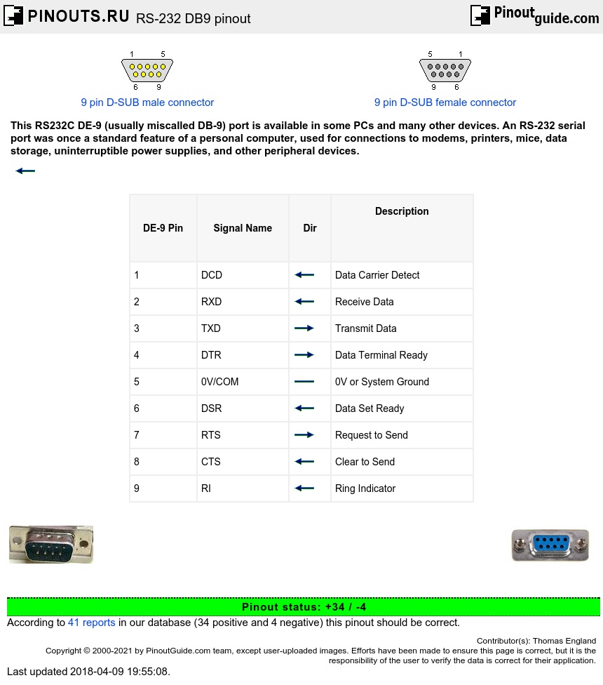

COMMENTS
25-pin serial pinout: Pin 1: GND − Shield Ground. Pin 2: TxD → Transmitted Data. Carries data from the Data Terminal to the Data Set. Pin 3: RxD ← Received Data. Carries data from the Data Set to the Data Terminal. Pin 4: RTS → Request to Send. Data Terminal signals the Data Set to prepare for data transmission.
A DB-25 connector as described in the RS-232 standard Data circuit-terminating equipment (DCE) and data terminal equipment (DTE) network. In telecommunications, RS-232 or Recommended Standard 232 is a standard originally introduced in 1960 for serial communication transmission of data. It formally defines signals connecting between a DTE (data terminal equipment) such as a computer terminal or ...
The standard specifies the electrical voltage levels, signal timing, and connector pin assignments for serial communication. Despite the emergence of newer protocols, RS232 retains its significance in certain applications, thanks to its simplicity and widespread support. ... such as RS-232, UART, SPI, and I2C, to transmit data over long ...
Pinout of RS-232 (EIA-232) serial interface and layout of 25 pin D-SUB male connector and 25 pin D-SUB female connectorRS-232 is the standard serial communications interface found on many types of equipment such as computers, modems, printers, Microcontrollers, eprom programmers, and a host of other devices. RS232 pinout may be varied.
Flash Memory Programming. GaAsFET Bias Generators. High Voltage Charge Pumps. Regulated Buck-Boost Charge Pumps. Regulated Inverting Charge Pumps. Regulated Step-Down Charge Pumps. This application note provides a detailed overview of the RS-232 specification. Find the full information and App Notes from Maxim Integrated.
Table 1 illustrates the signals that are defined by the RS-232 standard. As can be seen from the table there is an overwhelming number of signals defined by the ... RS-232 CONNECTOR PIN ASSIGNMENTS Figure 2 1 DATA SET READY (DSR) REQUEST TO SEND (RTS) CLEAR TO SEND (CTS) RING INDICATE (RI) DATA CARRIER DETECT (DCD)
RS-232 is a serial communication standard that, despite its age, still has a variety of uses in today's digital landscape. This article dives into the intricacies of RS-232, starting with a basic understanding of what it is, followed by its pin assignments, V.24 and V.28 interfaces, and an explanation of the Null Modem concept.
RS-232 defines the meaning of the different serial signals and their respective pin assignments on a standard 25-pin (DB-25) serial connector. Table 1 (a plain text version is also available) shows these assignments. Luckily, in standard types of communications only 9 of these pins are important: 1-8, and 20.
The RS232 devices work on single-ended signaling (two wire). This means one wire transmits an altering voltage and another wire is connected to ground. Single-ended signals are affected by the noise induced by differences in ground voltages of the driver and receiver circuits.
Serial Port Signals and Pin Assignments. Serial ports consist of two signal types: data signals and control signals. To support these signal types, as well as the signal ground, the RS-232 standard defines a 25-pin connection. However, most PCs and UNIX ® platforms use a 9-pin connection. In fact, only three pins are required for serial port ...
Pin Assignments Next Topic | Previous Topic | TOC. Go to DTE Pinout (looking into the computer's serial connector) Go to DCE Pinout (looking into the modem's serial connector). If the full EIA232 standard is implemented as defined, the equipment at the far end of the connection is named the DTE device (Data Terminal Equipment, usually a computer or terminal), has a male DB25 connector, and ...
The diagrams show the signals common to both connector types in black. The signals only present on the larger connector are shown in red. ... RS232 DB 9 Pin Assignment: RS232 DB 25 Pin Assignment: DEC MMJ Pin Assignment. DB9 to DB25 converter. The original pin layout for RS232 was developed for a 25 pins D sub connector. From IBM-AT machine ...
At the heart of the RS-232 cable lies the DCD pin, signaling the detection of a carrier signal, often vital in modem communications. Pin 2: Receive Data (RX or RxD) The RX pin stands as the welcoming gateway, ready to accept incoming data from the transmitting device, establishing the foundation of communication. Pin 3: Transmit Data (TX or TxD)
RS-232 signals are indicated by voltage differences with respect to a ground ... MECHANICAL Each line in an RS-232 interface is assigned a pin number for the various connectors that RS-232 can use. The nine primary lines, and their assignments in DB-9 and DB-25 connectors, are described in "Connectors and cables" on page 14. Synchronous vs ...
External Interfaces/API. Serial Port Signals and Pin Assignments. Serial ports consist of two signal types: data signals and control signals. To support these signal types, as well as the signal ground, the RS-232 standard defines a 25-pin connection. However, most PC's and UNIX platforms use a 9-pin connection.
The following table lists commonly used RS-232 signals and pin assignments. Signal Direction Connector pin; Name V.24 circuit Abbreviation DTE DCE DB-25 DE-9 MMJ 8P8C (RJ45) 10P10C (RJ50) EIA/TIA-561 Yost (DTE) Yost (DCE) Cyclades ... Connecting this to pin 7 (signal reference ground) is a common practice but not recommended. Some Cyclades ...
The RS-232 standard. The RS-232 Interface Standard was developed for a single purpose which is clearly stated in its title, the "Interface between Data Terminal Equipment (DTE) and Data Circuit Terminating Equipment (DCE) employing serial binary data interchange". In particular, EIA-232 was developed for interfacing data terminals to modems.
An RS232 pinout 9 pin cable features nine pins: 1. Data Carrier Detect - After a data terminal is detected, a signal is sent to the data set that is going to be transmitted to the terminal. 2. Received Data - The data set receives the initial signal via the receive data line (RxD). 3.
serial communications. The standard specifies connector types, pin assignments, voltage levels, etc. Even though the ... and what handshaking signals are needed for each device. ... The normal connector used for an RS-232 DTE device is a 9-pin male D connector. Older devices used a 25-pin male D
Pinout of PC serial port (RS-232 DE9) and layout of 9 pin D-SUB male connector and 10 pin IDC male connectorThis RS232C DE-9 (usually miscalled DB-9) port is available in some PCs and many other devices. An RS-232 serial port was once a standard feature of a personal computer, used for connections to modems, printers, mice, data storage, uninterruptible power supplies, and other peripheral ...
IBM PC/XT/AT RS-232 Serial Port Pin Configurations ... Standard RS-232-C Pin Assignments ... 7 AB/102 Signal Ground None 8 CF/109 Received Line Detect From DCE 9 ── For Testing 10 ── For Testing 11 **/116 Unassigned 12 SCF Second Received Line Detector From DCE ...
RS-422 only specifies the electrical signaling characteristics of a single balanced signal. Protocols and pin assignments are defined in other specifications. The mechanical connections for this interface are specified by EIA-530 ... For RS232 compatibility the TX/TXD+ signal must get routed to pin 3 (DTE) The second driver is used for RTS in ...