Open Access is an initiative that aims to make scientific research freely available to all. To date our community has made over 100 million downloads. It’s based on principles of collaboration, unobstructed discovery, and, most importantly, scientific progression. As PhD students, we found it difficult to access the research we needed, so we decided to create a new Open Access publisher that levels the playing field for scientists across the world. How? By making research easy to access, and puts the academic needs of the researchers before the business interests of publishers.
We are a community of more than 103,000 authors and editors from 3,291 institutions spanning 160 countries, including Nobel Prize winners and some of the world’s most-cited researchers. Publishing on IntechOpen allows authors to earn citations and find new collaborators, meaning more people see your work not only from your own field of study, but from other related fields too.
Brief introduction to this section that descibes Open Access especially from an IntechOpen perspective
Want to get in touch? Contact our London head office or media team here
Our team is growing all the time, so we’re always on the lookout for smart people who want to help us reshape the world of scientific publishing.
Home > Books > Finite Element Analysis - Applications in Mechanical Engineering

Finite Element Analysis Applications in Failure Analysis: Case Studies
Submitted: 23 April 2012 Published: 10 October 2012
DOI: 10.5772/51024
Cite this chapter
There are two ways to cite this chapter:
From the Edited Volume
Finite Element Analysis - Applications in Mechanical Engineering
Edited by Farzad Ebrahimi
To purchase hard copies of this book, please contact the representative in India: CBS Publishers & Distributors Pvt. Ltd. www.cbspd.com | [email protected]
Chapter metrics overview
6,719 Chapter Downloads
Impact of this chapter
Total Chapter Downloads on intechopen.com
Total Chapter Views on intechopen.com
Author Information
Ahmad ivan karayan.
- Department of Chemical and Biomolecular Engineering, The University of Akron, USA
Homero Castaneda
Deni ferdian.
- Department of Metallurgy and Materials Engineering, University of Indonesia, Indonesia
- Center for Materials Processing and Failure Analysis (CMPFA), University of Indonesia, Indonesia
Sri Harjanto
Dwi marta nurjaya, ahmad ashari.
*Address all correspondence to:
1. Introduction
The use of the finite element in engineering applications has grown rapidly in recent years. Finite element analysis (FEA) is based on numerical computation that calculates all parameters and boundaries given. Supported with powerful computer processors and continuous software development, the finite element method is rapidly advancing. The use of finite element analysis is not limited to the engineering field, as there are also medical and geospatial applications. The early development of the finite element can be traced back to the work of Courant [ 1 ], followed by the work of Martin [ 2 ], which applied the solutions for structural analyses at Boeing Company in the 1950s. Further work by Argyris, Clough, Turner, and Zienkiewicz developed the governing mathematical equation for the finite element method [ 3 ].
The numerical simulation introduced in the 70s for the stress model on concrete as published by Hillerborg [ 4 ] is a clear example of the FEA concept. Huiskes et al. [ 5 ] also stated that the finite element has been used in a structural stress analysis of human bones for biomechanic applications. Zienkiewicz et al. [ 6 ] applied the finite element method to the linear and non-linear problems encountered during the analysis of a reactor vessel. Gallagher [ 7 ] studied brittle material design through use of the finite element method, which incorporated thermal and elastic analysis aspects of the overall design. Miller et al. [ 8 ] used the finite element method during the study of crack stability of a turbine blade and proposed a hypothesis based on material strength characteristics, plastic zone size/history, and residual plastic strains.
In the mid 80s, Oritz et al. [ 9 ] proposed a method that aimed to enhance the performance of general classes of elements that undergo strain localization. An overview of the application of the finite element in machining from the 70-90s was well documented by Mackerle [ 10 ]. The application of the method to localize fractures was studied by Broberg [ 11 ], and further work was continued by Borst et al. [ 12 ]. Nowadays, finite element analysis is widely used by the engineering field in fluid dynamic and electrical applications.
In general, the finite element analysis is widely used in the pre-production manufacturing process to determine the most cost-effective decision based on the analysis. Finite element simulations allow comparison between different “designs.” Finite element analysis can simulate operational and environmental conditions and formulate modifications without creating a physical prototype.
In order to adequately determine the root cause of material failure, two outcomes are required: the answer and an explanation. The failure of a mechanical component is usually associated with materials, the environment, a third party, or human error. An investigation through metallurgical failure analysis is usually conducted to reveal the root cause and the failure mechanism. Work by Griffith [ 13 ] on fracture mechanics created a breakthrough in the understanding of the material fracture mechanism. In certain cases, a conventional failure analysis approach is not enough to reveal the failure, and therefore, a more comprehensive analysis through the finite element is needed. Prawoto et al. [ 14 ] explained that the use of the finite element is an effective approach when the causes of failure are determined using qualitative metallographic and fractographic testing. The finite element requires an understanding of how a component works and will support the correct information and data. The quality of the data provided is a key element for the successful outcome of the simulation.
2. The finite element in failure analysis
The use of finite element analysis in mechanical applications has heavily increased in recent years. The continuous efforts to improve calculations and analyses so that models accurately incorporate actual conditions have been rewarded as a consequence of computer tool evolution. The finite element analysis has become an important tool for improving the design quality in numerous applications. The finite element analysis is a computer-based technique to solve problems using numerical solutions. The analysis includes a method based on creating a geometrical model of the structure that is divided into individual nodes or elements.
Finite element modeling provides different insights into the engineering analysis that cannot be obtained with the classical failure analysis method. Classical commercial software such as ABAQUS® and ANSYS® has been widely used to analyze failures or defects and reconstruct possible root causes. The images and animation produced by the software help to give a better understanding by visualizing the root cause behind the failure event. Previously, the development of the finite element evolved slowly due to a lack of tools to solve mathematical equations, and therefore, the method remained dormant until the computer era.
The early finite element software was commissioned by NASA in mid 1960s, which introduced NASTRAN® as an application that helped to design more efficient structures for vehicles that were developed by them [ 15 ]. The ANSYS® software, which was released in 1970, was run on a massive mainframe computer that was less powerful than the personal computers of today [ 16 ]. The early software was only capable of simulating the 2D beam model, but it eventually progressed towards the modern 3D solid model of today as computer hardware developed.
The applications of finite element analysis in engineering failure analysis are in continuous evolution as more factors related to the failure event are taken into account. For example, in the case of turbine blades involved in jet engine failure, engineers should incorporate the thermal effect and load effect received by the blade in the simulation, not to mention other possibilities from foreign particles that could initiate the failure. Therefore, FEA calculations now incorporate a combination of multiple physical environments. Current research related to the application of the finite element in failure analysis has been published in peer-reviewed journals, and can be seen in publications such as Engineering Failure Analysis Journal ® and Failure Analysis and Prevention Journal ®.
In general, a finite element method consists of three phases: (1) pre-processing, where the analyst creates the finite element mesh and applies certain parameters or boundaries to the model, (2) solver/solution, where the program runs the governing mathematical equation that was created by the model, and (3) post-processing, where the result is evaluated and validated for further interpretation.
Some limitations must be recognized in the finite element method. The ability to define and analyze the system and the model will determine the quality of the simulation results. The evaluations of any failure event need a comprehensive approach to reveal the root cause of the failure. FEA is a tool where multidisciplinary fields are combined to help find or support the solution with better accuracy for a final conclusion. Below are three case studies that illustrate how finite element analysis can be utilized in failure analysis.
3. FEA in mechanical failure
The use of FEA for mechanical failure has become a necessary tool that is easily obtained, as the commercial software is readily available for users. FEA is widely used in failure analysis assessment when analyzing and characterizing the quantitative and qualitative approaches used to determine the root cause of an event leading to a failure. The software is given historical background information related to the failure along with other boundary conditions. Below is an example of a mechanical failure analysis assessment that used finite element analysis software to verify the findings regarding the failure event.
In the first case, the finite element method was used to analyze the stress distribution of a failed 28MW horizontal hydroturbine shaft [ 17 ]. The data corresponded to the fractography and metallographic observations. The finite element analysis was performed for normal conditions as well as the type of high load conditions that would be experienced during the start-up period.
The shaft was constructed by the joining of a forged and cast part by slag welding. A crack was observed at the radius area of the casted part. The part was given an estimated 200,000 hours of operating life, and failure was detected after 163,411 hours in service. A visual examination of the fracture surface showed a fatigue pattern with obvious ratchet marks. Further observation of the fracture surface showed visible distorted fatigue lines around numerous gas holes and areas of increased porosity.
An original document indicated that the shaft was heat-treated to complete an austenization process. However, metallographic examination showed cast ferrite-pearlite with an undissolved dendrite structure, which might indicate that an improper heat treatment process occurred. In addition, a large non-metallic inclusion was also observed in the cast part.
A linear FEA was used to determine the stress state of the turbine shaft and shaft flange. The commercial ANSYS® software was used for the finite element modeling. The model represents a discrete continuum by an 8-node finite element with three degree of freedom that comprises 49,430 nodes and 47,547 elements. All of the boundary conditions were incorporated into the model.
A numerical calculation to determine the shaft flange stress states was performed for two characteristic load cases, where one load was taken from the manufacturer's documentation and the second load was the static load that occurs during start-up. Calculation of the finite element for both load conditions showed that the maximum stress was at the crack initiation site at the shaft flange.
The data collected from the chemical composition test and mechanical test showed that the material did not comply with the minimum standard required. Therefore, the crack location where the failure occurred was more susceptible to stress. Finite element analysis showed a high distribution of stress at the failed area. The finite element analysis revealed that the obtained tensile stress value on the shaft flange transition radius due to the load in case 2 was higher than recommended, and was characterized by the stress intensity factor at the crack tip being higher than the material threshold.
It was concluded that corrosion fatigue was the cause of the shaft failure [ 16 ]. The root cause for this case was improper corrosion protection at the failed area and a lack of periodical inspection, both of which were necessary due to the high stress on the region.
4. FEA in corrosion failure
Karayan et al. [ 18 ] studied the failure of a seawater inlet pipe. The failure was first characterized by a small leak at approximately the 4-8 o’clock position. A schematic drawing of the inlet pipe showing the backing bar near the leak location is shown in Figure 1 . This backing bar was installed on the welded surface. The visual examination of this failed pipe is shown in Figure 2 . In order to find out the root cause of failure, a number of laboratory tests were performed. The results showed that the failure was caused by cavitation, as evident by the presence of a crater-like surface near the backing bar ( Fig. 3 ). These localized craters seemed unusual since they were only noticed near the backing bar. An additional tool such as finite element analysis was used to determine why this was the case. A finite element analysis was executed based on the pipe dimension and actual fluid conditions such as velocity, pressure, temperature, and implicit parameters. Because there were no data for the initial height of the unwanted backing bar, the authors assumed that the initial height was the highest backing bar found on the specimen. Interestingly, the failure location predicted by the finite element analysis matched up with the actual evidence ( Fig. 4) . It precisely showed that the failure could be located around the backing bar where the eddy zone was formed in this area. This suggests that sometimes the results obtained from laboratory tests cannot explain why a failure occurs, although evidence indicates the existence of a certain problem. In this case, a finite element analysis is the only tool that can help a failure analyst find the root cause of failure. As can be seen from Figure 4 , the leaks and crater-like surfaces found in the area near the backing bar were attributed to the formation of eddy zones in this area. The length of the eddy zone predicted that the area that might suffer from a flow-induced attack.

Big and small leak near the backing bar at about 6 o’clock position viewed from the inner side of seawater inlet pipe.

Surface morphologies of brown crater – like surface taken from 6 – 3 o’clock position.

Finite element analysis of the inner pipe showing the orifice effect and the eddy zone near the backing bar correlated with the actual leaks on the inlet pipe.
The last case is a trunkline that burst during service [ 19 ]. This incident produced a significant impact on the gas production of the company and also on the environment. The failure was characterized by a mesa-like attack and wall thinning at the 5-7 o’clock position on the inner surface. The location of failure is shown in Figure 5 . A reddish brown corrosion product was noticed on the surface, but there with no indication of the occurrence of an H 2 S attack found in the material. This trunkline, carrying the gas with a total pressure of 905 psi, spanned across the jungle in the descending position. The analysis of the gas composition is listed in Table 1 . The topography and characteristics of the soil in which the trunkline was located and also the material specification data is listed in Table 2 .

The specimen sent to the laboratory for analysis is indicated by arrow
Result of gas analysis in trunkline
Fluid properties and failed trunkline condition.
A visual examination showed that the burst area was located at the 6 o’clock position of the (a) downstream part and the (b) upstream part ( Fig. 6 ). Some points on the inner surface of the downstream part at the 5-7 o’clock position showed surface degradation with wall thinning and pits ( Fig. 7 ). Some points on the inner surface of the upstream part at the 5-7 o’clock position also showed surface degradation with wall thinning and pits ( Fig. 8 ). A uniform attack at the burst area from the 5-7 o’clock position is shown in Figure 9 .

a) Downstream part and (b) upstream part showing the burst located at 6 o’clock position.

Wall thinning and pits at 5 – 7 o’clock position of downstream part.

Wall thinning and pits at 5 – 7 o’clock position of upstream part.

Uniform attack at the burst area from 5-7 o’clock position.
The metallographic preparation and macroetching were performed on the perimeter of the trunkline, and the results showed that the trunkline was made of seamless pipe ( Figs. 10 and 11 ). The thinning area shown in Figure 9 was an ERW (electric resistance welding)-free area ( Fig. 10 ). This information indicates that the failure could not be attributed to the ERW pipe issue.

Results of macroetching showing the absence of ERW.

Macrograph of 5-7 o’clock position showing the absence of ERW.
The microstructure of the trunkline was taken from the cross-section, and the results are displayed in Figure 12 . As can be seen, the trunkline is composed of ferrite (light phase) and pearlite (dark phase) with equiaxed grains, which is typical of seamless pipe. The chemical composition of the trunkline was tested using an optical emission spectrometer and the results ( Table 3 ) show that this trunkline is composed of an API 5L X60 steel [ 20 ]. Due to the insufficient geometry of the trunkline, the mechanical property of the trunkline was only examined by hardness testing. In order to verify that the specification of this material was API 5L, the resultant hardness values were converted to tensile strength ( Table 4 ).

Microstructure of trunkline showing a typical seamless microstructure with equiaxed grains. The dark phase is pearlite and the light one is ferrite.
Chemical composition of trunkline
Converted tensile strength in comparison with API 5LX60 specification.
The finite element analysis was executed around the overfill, and the results ( Fig. 13 ) showed that the area at which the pipe burst had a dead or eddy zone due to the excessive overfill ( Figs. 14 and 15 ). Because there was no information about the initial overfill height, we assumed an overfill height of 1 cm for the finite element simulation. This selection was based on the fact that there was one point at the remaining overfill that had a height of 1 cm. The other areas were mostly degraded, with heights of less than 0.5 cm. Severe corrosion was noticed on every peak of overfill.

Finite element analysis showing the eddy zone due to overfill in comparison with the actual failed area of pipe.
As can be seen in Table 1 , the only corrosive gas in the fluids flowing in this failed trunkline was CO 2 . Carbon dioxide systems are one of the most common environments in the oil and gas field industry where corrosion occurs. In a relatively slow reaction, carbon dioxide forms a weak acid known as carbonic acid (H 2 CO 3 ) in water, but the corrosion rate of CO 2 is greater than that of carbonic acid. Cathodic depolarization may occur, and other attack mechanisms may also occur. The presence of salts is relatively unimportant in sweet (CO 2 ) service [ 21 ], and thus, the presence of chloride in this system (0.7635%) did not significantly contribute to the failure.

The inner side of circle area in Fig. 11 showing an excessive overfill (arrow) in the failed pipe at 12 o’clock position.

An excessive overfill and severe surface degradation beside overfill at 6 o’clock position.
The sweet environment of this system with a CO 2 partial pressure of 17.56 psig may influence the presence of corrosion. The relationship between corrosion tendency and CO 2 partial pressure in the sweet environment with pH 7 or less has been reported elsewhere [ 22 ]. When the CO 2 partial pressure is less than 7 psig, the system is non-corrosive. When it is somewhere between 7-30 psig, corrosion in the system may be present. Lastly, when it is higher than 30 psig, the system is corrosive [ 22 ]. Temperature and flow regime are closely linked because CO 2 corrosion is dynamic and very sensitive to electrochemical and physical imbalances (especially fluctuating pressure, temperature, and volume). Steady-state (P,T,V,) conditions tend to promote protective film compaction, and therefore, passivation and low corrosion rates. Lower temperatures <120°F (approximately 50°C) tend to promote patchy corrosion with softer multi-layered iron carbonate (siderite) scales that provide some barrier protection up to 140-160°F (60-70°C). Above these temperatures, damaging localized corrosion is observed as films lose stability and spall off, giving rise to galvanic mesa attack [ 23 ]. The failed pipe we studied with an operating temperature of 140°F might have formed a protective film. However, the phenomenon of film removal and its effect on the failure of this trunkline was not evident in our laboratory test. Our finite element analysis in the failed area in Figure 13 shows the unstable and chaotic flow in the failed area (called the dead or eddy zone). As illustrated, the eddy zone was triggered by the excessive overfill. This suggests that the pipe surface in this eddy area was severely attacked by flow. The presence of a passive carbonate layer could not protect the surface from this type of flow-induced attack that led to a mesa attack.
5. Conclusions
The three case studies discussed in this chapter have clearly shown us that finite element analysis (FEA) is an excellent and powerful tool that can be employed in failure analysis. Finite element analysis provides a failure analyst with more quantitative and qualitative information about the causes of failure. Although visual examinations and laboratory tests may not be able to determine a failure mechanism, the results of finite element analysis will support all data obtained from these tests. As long as a competent analyst running the finite element analysis is given sufficient data and has good knowledge of the system under study, the results of FEA will be reliable, although they should always be validated with experimental or real condition information.
- 1. F. Williamson, Richard Courant and the finite element method: A further look, Historia Mathematica, Vol 7(4), 1980, pp. 369-378.
- 2. H. C. Martin, Large Deflection and Stability Analysis by Direct Stiffness Method, JPL Technical Report No. 32-931, California Institute of Technology, August 1966.
- 3. R. W. Clough, Early History Of The Finite Element Method From The View Point of a Pioneer, International Journal For Numerical Methods In Engineering, 60, 2004, pp. 283-287.
- 4. A. Hillerborg, M. Modéer, P.-E. Petersson, Analysis of crack formation and crack growth in concrete by means of fracture mechanics and finite elements, Cement and Concrete Research,Vol 6(6), 1976, pp. 773-781.
- 5. R. Huiskes, E.Y.S. Chao, A survey of finite element analysis in orthopedic biomechanics: The first decade, Journal of Biomechanics, Vol 16(6) 1983, pp. 385-409.
- 6. O.C. Zienkiewicz, D.R.J. Owen, D.V. Phillips, G.C. Nayak, Finite element methods in the analysis of reactor vessels, Nuclear Engineering and Design, 20(2) 1972 507 541
- 7. R.H. Gallagher, Finite element analysis in brittle material design, Journal of the Franklin Institute, 290(6) 1970 523 537
- 8. R.E. Miller Jr., B.F. Backman, H.B. Hansteen, C.M. Lewis, R.A. Samuel, S.R. Varanasi, Recent advances in computerized aerospace structural analysis and design Computers & Structures, 7(2) 1977 315 326
- 9. M.Ortiz, Y.Leroy, A.Needleman, A finite element method for localized failure analysis, Computer Methods in Applied Mechanics and Engineering, Vol 61(2) 1987, pp. 189-214.
- 10. J. Mackerle, Finite-element analysis and simulation of machining: a bibliography (1976-1996), Journal of Materials Processing Technology, Vol 86, Issues 1-3, 1998, pp. 17-44.
- 11. K.B. Broberg, The foundations of fracture mechanics, Engineering Fracture Mechanics,Vol16(4) 1982 497 515
- 13. Griffith: Phil Trans Roy Soc 1921 221 163 198
- 14. Y.Prawoto, Quantitative failure analysis using a simple finite element approach. Journal of Failure Analysis and Prevention, 10 (1) 2010 8 10
- 15. http://en.wikipedia.org/wiki/Nastran
- 16. http://www.odonnellconsulting.com/forensicfea.html
- 17. D. Momcilovic, Z. Odanovic, R.Mitrovic, I.Atanasovska, T.Vuherer, Failure analysis of hydraulic turbine shaft, Engineering Failure Analysis, 20 (2012) pp. 54-66.
- 18. A.I. Karayan, A. Hersuni, D. Adisty, A. Yatim, Failure analysis of seawater inlet pipe, Journal of Failure analysis and Prevention, 11(2011) pp. 481-486.
- 19. A.I. Karayan, Failure Analysis of Trunkline: An Internal Report, Center for Materials Processing and Failure Analysis (CMPFA), 2011.
- 20. American Petroleum Institute (API) L Standard.
- 21. http://octane.nmt.edu/WaterQuality/corrosion/CO2.aspx
- 22. Garverick L, Corrosion in the petrochemical industry, pp. 92, ASM International, 1994.
© 2012 The Author(s). Licensee IntechOpen. This chapter is distributed under the terms of the Creative Commons Attribution 3.0 License , which permits unrestricted use, distribution, and reproduction in any medium, provided the original work is properly cited.
Continue reading from the same book
Finite element analysis.
Published: 10 October 2012
By P.H. Darji and D.P. Vakharia
3680 downloads
By Toshihiro Saito
3892 downloads
By Jairo A. Martins and István Kövesdy
3382 downloads
Academia.edu no longer supports Internet Explorer.
To browse Academia.edu and the wider internet faster and more securely, please take a few seconds to upgrade your browser .
Enter the email address you signed up with and we'll email you a reset link.
- We're Hiring!
- Help Center

Case Studies in Engineering Failure Analysis

Diversion due to coil break in cold rolled non oriented (CRNO) grades of coils showed an increasing trend during Jan–May’12 at Silicon Steel Mill (SSM), Rourkela Steel Plant (RSP). Coil break increased from a level of less than 1% during to a level of 30% in May’12. Samples from hot rolled coils and finished coils were taken and detailed metallurgical investigation was carried out to ascertain the genesis of such defects. Further studies were carried out in the processing lines and material flow was tracked from steel making to final product. The probable reasons were identified and corrective measures were taken leading to reduction in diversion due to coil break less than 2%.
Related Papers
Suman Kant Thakur
Diptak Bhattacharya
A metallurgical analysis of longitudinal cracks in a medium carbon grade of steel, produced through Thin Slab Casting and Rolling (TSCR) process is presented in this paper. Using characterization techniques, it was established that the defect originated from the funnel mold of thin slab caster. Temperature profiles of thermocouples in caster mold were employed to evaluate the heat transfer characteristics during primary solidification. The profiles helped to assess the performance of a standard mold flux used for casting this grade and hypothesize a possible mechanism of defect evolution. Slightly changed characteristics of the mold flux addressed the defect by promoting a stable and uniform heat transfer. This drastically lowered defect occurrence and rejections due to longitudinal cracks in this grade.
jorge barrera
PANKAJ NARAYAN CHAUDHARY
Failures of rolls occur due to improper manufacturing and operational parameters. The samples of prematurely failed roll samples collected from steel plant were examined for their chemistry, inclusion content, microstructures, carbide characteristics, hardness and the retained auste¬nite content. The residual stresses were also measured on the inner as well as the outer surface of the spalled roll pieces. The results obtained have been discussed in this paper. The higher content of retained austenite was primarily responsible for the spalling of indigenous rolls for which sub zero treatment has been recommended. Several suggestions have also been made for smooth operation of the mill and consequently for the ex¬tension of life of a work roll.
Keenanda davine
Metallurgical and Materials Engineering
Goran Vukićević
Goutam Mukhopadhyay
Engineering Failure Analysis
Paulo Belotti
Sandip Bhattacharyya
IRJET Journal
A spinning machine component known as a shaft transfers power from one place to another. Power transmission causes the shaft to receive torque, and reactions to the members it supports cause the shaft to receive a bending moment. The shaft was modified to include a discontinuity for crucial functional requirements. The shaft supports a variety of loading situations while it is in use (torsion, bending, axial, and combinations of these). In order to better understand failure and find ways to prevent it, a coil car shaft study was done. A visual inspection, hardness measurement, and investigation were carried out to determine the integrity of the failed axle shaft. The findings indicate that reversed bending fatigue caused the axle shaft to fracture and that fractures occasionally happened as a result of misalignment. A common cause of failure for many rotating equipment components is fatigue fracture.
RELATED PAPERS
Lince Mukkun
Proceedings (Baylor University. Medical Center)
Heidi Frankel
Jurnal Gradasi Teknik Sipil
Ahmad Marzuki
The Annals of Iowa
TERESA AZUARA
Journal of Cataract & …
Proceedings of the Winter Simulation Conference 2014
José Sepúlveda
International Urogynecology Journal
Nature Climate Change
Mélusine Boon Falleur
Marina R Caivano
Natacha Bacolla
Journal of Pharmacy and Bioallied Sciences
Shafiqul Islam
Joana Silva
RSC Advances
Dariush Saberi
Jurnal Ekonomi dan Bisnis
Muhamad Syafii
Frenette Southwood
Proceedings of the conference on Ethics in the computer age -
Gregory White
Revista Brasileira de Atividade Física & Saúde
Thiago Andrade de Sousa
Brooke Hallowell
Ciencia e Investigación
AMPARO IRIS ZAVALETA PESANTES
Arabian Journal of Geosciences
Mujibur Rahman
Immunological Investigations
Ema Paulovičová
Machmudin Prasetya
IEEE Journal of Oceanic Engineering
Jezik : časopis za kulturu hrvatskoga književnog jezika
Jelena Vignjevic
Educação crítica de línguas/linguagens em grupos de estudos
Milena O . Reis
See More Documents Like This
RELATED TOPICS
- We're Hiring!
- Help Center
- Find new research papers in:
- Health Sciences
- Earth Sciences
- Cognitive Science
- Mathematics
- Computer Science
- Academia ©2024

An official website of the United States government
The .gov means it’s official. Federal government websites often end in .gov or .mil. Before sharing sensitive information, make sure you’re on a federal government site.
The site is secure. The https:// ensures that you are connecting to the official website and that any information you provide is encrypted and transmitted securely.
- Publications
- Account settings
Preview improvements coming to the PMC website in October 2024. Learn More or Try it out now .
- Advanced Search
- Journal List
- Saf Health Work
- v.1(1); 2010 Sep
A Case Study on Engineering Failure Analysis of Link Chain
1 Department of Occupational Health and Safety Engineering, Inje University, Gimhae, Korea.
Seong-Beom Lee
2 High Safety Vehicle Core Technology Research Center, Inje University, Gimhae, Korea.
Hong-Chul Lee
3 Aero Technology Research Institute, Daegu, Korea.
The objective of this study was to investigate the effect of chain installation condition on stress distribution that could eventually cause disastrous failure from sudden deformation and geometric rupture.
Fractographic method used for the failed chain indicates that over-stress was considered as the root cause of failure. 3D modeling and finite element analysis for the chain, used in a crane hook, were performed with a three-dimensional interactive application program, CATIA, commercial finite element analysis and computational fluid dynamic software, ANSYS.
The results showed that the state of stress was changed depending on the initial position of the chain that was installed in the hook. Especially, the magnitude of the stress was strongly affected by the bending forces, which are 2.5 times greater (under the simulation condition currently investigated) than that from the plain tensile load. Also, it was noted that the change of load state is strongly related to the failure of parts. The chain can hold an ultimate load of about 8 tons with only the tensile load acting on it.
The conclusions of this research clearly showed that a reduction of the loss from similar incidents can be achieved when an operator properly handles the installation of the chain.
Introduction
Industrial disasters have increased in proportion to the development of industry. While industrial disasters in our country have decreased annually, the rate of our disasters is still higher than that of industrially advanced nations [ 1 ]. Various efforts are needed to reduce industrial disasters. Four major phenomena, including insertion/winding, conduction, falling and collision, should be thoroughly studied because they account for 62.3 percent of all industrial disasters [ 2 ] that are classified by failure mode. It is reported that disasters are more likely to occur when the operator does not follow proper procedures.
In this study, 3-dimensional (3D) modeling and FE analysis were per formed to identify the correct and incorrect installation pro cedures of link chain, and identify factors which could lead to disastrous failures from the incorrect installation. A chain ( Fig. 1 ), consisting of consecutively connected metal rings, is usually used to crane heavy weight materials and hot parts in industry, due to its rigidity and strong resistance to heat and corrosion [ 3 ]. The results show that a method to reduce the rate of disasters could be identified by quantifying the effect of the worker's incorrect handling of the chain link procedure.

Chain specimen of original crane chain.
Materials and Methods
This study utilized 3D modeling and finite element analysis [ 4 - 6 ] of the chain which is used in the crane to estimate the effect of different load cases on structural rigidity. CATIA [ 7 ], three-dimensional interactive application program was used for 3D modeling of the chain and ANSYS [ 8 - 11 ], commercial finite element analysis software was used for this analysis.
Fractographic analysis
Before performing stress analysis for crane chain, observation of the fracture surface of the failed chain was conducted in order to understand the possible failure mechanism. This procedure helped us to identify the guideline to further analyze the failure mechanism mainly in two conditions which are discussed in detail in the following section.
After failure of the crane chain occurred, a fractured chain was sent to a metallurgical laboratory to identify the failure mechanism and its root cause. As shown in Fig. 2 , the width of the ruptured chain ring was shrunk by deformation when the chain failed, without retaining its original shape. The fracture surface which was formed at an angle of 30-45° to the primary load direction, clearly shows the shear fracture. In a macroscopic view, both fracture surfaces of the crane chain show a shear fracture ( Fig. 3 L/H ) and the cup and cone shape ( Fig. 3 R/H ), of which phenomena are considered as evidence of catastrophic failure due to improper overload. Especially, Fig. 3 L/H shows a shear fracture with crushed damage formed by the compressive load on the side of the chain. To analyze the fracture surfaces, each part was viewed with a scanning electron microscope. As shown in Fig. 4 , the fracture surface having the shape of cup and cone as an enlarged area of Fig. 3 R/H shows the equiaxed dimples in the flat surface and the elongated dimples in the inclined region. Elongated or equiaxed dimples are observed inside the fracture surface. Fig. 4B and and5C 5C show the step-like topographies indicating the fracture due to bending moment rather than uniaxial tension. Also, as shown in Fig. 4D , cleavage fracture surface is usually formed under high strain rate loading condition. Therefore, it is considered that the fracture of the crane chain was occurred under high strain rate bending moment rather than uniaxial tension instantaneously.

Failed crane chain.

Photographs of normal crane chain.

Higher-magnification view of fracture surfaces ( Fig. 3 R/H ) reveal dimple rupture.

Higher-magnification view of fracture surfaces ( Fig. 3 L/H ) reveal dimple rupture and step-like topography formed by overload.
FE modeling and material
A quarter model of the chain's configuration was generated by CATIA, because the dimension of the crane chain is symmetrical with respect to longitudinal and horizontal axes. A cross sectional area of the chain was assumed to be constant, without considering the irregularities of the welding zone. The quarter model of the crane chain generated in CATIA and input to ANSYS for the analysis is shown in Fig. 6 . The number of nodes and elements used for a quarter of the FE chain model are shown in Table 1 .

Three-dimensional (3D) models of crane chain. (A) 3D model generated in CATIA. (B) 3D model imported in ANSYS model.
The number of nodes and elements

Results of chemical analysis in Table 2 show that the material of the crane chain is American Iron and Steel Institute (AISI) 8622 steel. The chain made of AISI 8622 steel has a yielding strength of 805 MPa, an ultimate strength of 1204 MPa, an elastic modulus of 205 GPa, and a Poisson's ratio of 0.25. The material properties of AISI 8622 steel are also shown in Table 3 .
Chemical analysis of failed crane chain

AISI: American Iron and Steel Institute.
Mechanical properties of failed crane chain

AISI: American Iron and Steel Institute, HRC: Rockwell hardness C scale.
Analysis condition and method
The failure of the crane chain attached to the hook occurs under the influence of a mixture of various excessive loads. Fur thermore, the residual stress is also generated in the welding zone of the chain because the temperature gradient and thermal stress were formed by irregular heating during the welding process [ 12 ].
This study did not deal with the surface fatigue cracks initiated by the result of long-term usage and surface defects, which accounted for about 60-70 percent of the causes of machine element failure [ 13 ]. Due to absence of a fatigue test machine for chain, the current study concentrated on the simple two load conditions, tension and bending, that could occur depending on the installation condition of the hoisting hook which is demonstrated in Fig. 7 [ 14 ]. In this research, FE analyses for the chain were performed when the tensile and bending load were acting on it with the symmetric state as the boundary condition. Fig. 7A is the properly installed connecting chain which is linked up with the hoist hook. On the other hand, Fig. 7B shows the improper installation of a smaller chain whose outside surface is directly contacting the hoist hook.

The state of loading condition with respect to the installation of crane chain. (A) Correct installation: tension load. (B) Incorrect installation: bending load.
A symmetrical boundary condition was applied in the FE model with one quarter of the chain configuration. The section area suffered loads is subjected to a symmetry boundary condition, namely displacement of vertical direction on area is zero. The other one is zero displacement in DOFs. The analysis was conducted under the various load conditions with the magnitude acting on the cross section of the chain. The applied boundary and load conditions of the crane chain are shown in Figs. 8 and and9 9 .

Boundary and tension load condition for FE crane chain model.

Boundary and bending load condition for FE crane chain model.
Results and Discussion
Analysis with respect to load state.
Using the ANSYS FEA software, we calculated the stress distribution under the condition that the axial tensile load acts on the chain. Also, the stress distribution was analyzed when the bending load was applied to the chain. Fig. 10 shows the results of the ANSYS analysis when tension is applied.

Von-Mises stress distribution (tension 5 ton).
Fig. 11 shows the results of the ANSYS analysis when a bending load is applied. From the numerical analysis, the results show that the maximum Von-Mises stress is 455 MPa from ANSYS under axial tension. When the bending moment is applied, the stress is 1,236 MPa. Considering the case of five tons of tensile load, the analysis result computed from FE analysis is approximately 460 MPa, which is lower than that of the yield strength of the material. On the contrary, when five tons of bending load is applied, the result amounts to approximately 1,180 MPa, nearly reaching the ultimate strength (1,204 MPa). Also the result shows that the stress magnitude occurred by a bending force is 2.5 times greater than that of a plain tensile load. From the results, we are sure that the magnitude of stress is heavily dependent on the stress state acting on the fracture surface.

Stress analysis results (bending 5 ton).
Material properties of chain
Results of chemical analysis and a hardness test show that the failed chain was an AISI 8622 steel alloy. Chemical analysis and mechanical properties of the failed crane chain are summarized in Tables 2 and and3. 3 . In this alloy, nickel in combination with chromium, produces low-alloy steel with higher elastic limits, greater hardening capability, and higher impact and fatigue resistance than plain-carbon steel. The further addition of about 0.2% Mo increases hardening capability even more and minimizes the susceptibility of these alloys to temper embrittlement. This alloy is used for shafts and many other applications in forgings which require high strength.
Maximum allowable load
From the experimental simulations conducted with respect to various load cases, it was found that the chain can hold an ultimate load of about 8 tons when the tensile load acts on it as shown in Fig. 12 . In this case, the maximum Von-Mises stress amounts to 729 MPa in ANSYS, which is slightly lower than that of the yield strength (805 MPa) of the material, AISI 8622 steel.

Stress analysis results (tension 8 ton).
Conclusions
In this research, structural safety of a crane chain was investigated through the prediction of the chain's material behavior and the calculation of maximum allowable load with respect to tension and bending loads. The results are summarized as follows.
- The fractographic analysis of the failed part reveals that the crane chain was fractured catastrophically by the bending forces.
- The results of finite element analysis show that the state of stress is strongly affected by the condition of the chain installed in the hook, due to the fact that the stress magnitude caused by bending forces is 2.5 times greater than that of the plain tensile load.
- FEA results are in accordance with the fractographic analysis, in that the change of load condition from tension to bending severely affects the failure of parts.
Furthermore, detailed analysis is recommended to consider residual stress in the welding zone and various changes of load condition in order to further refine the fracture mechanism analysis.

Information for Faculty
- Bridge Failure Cases
- Dam Failure Cases
- Building Failure Cases
- Other Failure Cases
There is a documented need for failure awareness in the undergraduate engineering curriculum. Engineering students can learn a lot from failures, and failures play an important role in engineering design. This need has been expressed in a number of papers and at a number of conferences over the past two decades. This book is a specific response to that need and will provide (1) much needed access to examples, and (2) a heightened appreciation of the role failure analysis knowledge can play in higher education and public safety.
Many of the key technical principles that civil engineering students should learn can be illustrated through case studies. For example, the author has discussed the Hyatt Regency walkway collapse, the Tacoma Narrows Bridge failure, and other well-known cases with students in Statics, Mechanics of Materials, and other courses. These cases help students:
- Grasp difficult technical concepts and begin to acquire an intuitive feel for the behavior of systems and structures,
- Understand how engineering science changes over time as structural performance is observed and lessons are learned,
- Analyze the impacts of engineering decisions on society, and
- Appreciate the importance of ethical considerations in the engineering decision making process.
The main obstacle to integrating case studies and lessons learned from failures into existing courses has been that many faculties does not have time to research and prepare case studies. Although there are many references available, they are difficult to translate into classroom lectures without considerable added effort on the part of the instructor.
There are three ways to introduce failure analysis and failure case studies into civil engineering education. A small number of colleges and universities, probably only a few percent, offer courses in forensic engineering or failure case studies. Often, these are at institutions such as the University of Texas, Mississippi State University, or the University of Colorado at Denver that have practicing forensic engineers on the faculty (Delatte and Rens, 2002). Clearly, this approach depends on the availability of qualified and interested faculty.
Another method is to use case studies in capstone (Senior) design projects (Delatte and Rens, 2002). This is also dependent on the interested and qualified faculty, as well as on the availability of appropriate projects (which must be sufficiently free of liability concerns).
These two approaches offer great depth in the topic, but due to their inherent limitations, their application is likely to remain limited. As a result, even at colleges and universities where courses are offered in this area, few undergraduates are likely to be able to take them. While some might argue for a required stand-alone course in failure analysis for all undergraduate civil engineering students, the argument is likely to fall on deaf ears as programs shrink their credit hour requirements. However, this book would be an excellent text for a civil engineering failure analysis course.
A more promising approach is to integrate failure case studies into courses throughout the curriculum. Many professors have done this on an informal basis for years. The author used this approach at the United States Military Academy (USMA) while teaching two courses in engineering mechanics, Statics and Dynamics and Mechanics of Materials (Delatte, 1997). He continued the approach in engineering mechanics and civil engineering courses at the University of Alabama at Birmingham (UAB) (Delatte, 2000, Delatte and Rens, 2002, Delatte, 2003) and at Cleveland State University.
Why Study Failures?
In a survey conducted by the ASCE Technical Council on Forensic Engineering (TCFE) Education Committee in December 1989, about a third of the 87 civil engineering schools responding indicated a need for detailed well-documented case studies. The University of Arizona said ASCE should provide such materials for educational purposes and Swarthmore College suggested ASCE should provide funds for creating monographs on failures that have occurred in the past (Rendon 1993a).
The ASCE TCFE conducted a second survey in 1998, which was sent to all Accreditation Board for Engineering and Technology (ABET) accredited engineering schools throughout the United States (Rens et al, 2000a). Similar to the 1989 survey, the lack of instructional materials was cited as a reason that failure analysis topics were not being taught. One of the unprompted written comments in that survey was a selected bibliography is needed on the topic, which could be accessed via the Internet.
The use of case studies is also supported by the latest pedagogical research. From Analysis to Action ( Center, 1996) refers on page 2 to textbooks lacking in practical examples as an emerging weakness. Much of this document refers specifically to the breadth of understanding, which may be achieved through case studies. Another issue addressed (Center, 1996, p. 19) is the need to incorporate historical, social, and ethical issues into courses for engineering majors. The Committee on Undergraduate Science Education in Transforming Undergraduate Education in Science, Mathematics, Engineering, and Technology (Committee, 1999) proposes that as many undergraduate students as possible should undertake original, supervised research. How People Learn (Bransford et al., 1999, p. 30) refers to the need to organize knowledge meaningfully, in order to aid synthesis and develop expertise.
This work raises the question of whether failure analysis is merely tangential to, or is, in fact, fundamental to, civil engineering education. Put another way, are failure case studies simply interesting, or should they be an essential component of a civil engineering curriculum?
Failure Case Studies and Accreditation Requirements
ASCE TCFE Education Committee surveys of civil engineering departments reported in 1989 and 1998 (Rendon-Herrero, 1993a, 1993b, Bosela, 1993, Rens et al., 2000) found that many respondents indicated a need for detailed, well-documented case studies. Some of those replying felt strongly that incorporation of failure case studies should not become part of accreditation evaluations. However, unless something is specifically mandated by the Accreditation Board for Engineering and Technology (ABET), it is likely to be a low priority for inclusion in a curriculum.
There is certainly an argument to be made that failure analysis should be mandated by ABET. It may also be argued that, in a sense, it already is. Under Criterion 3, Program Outcomes and Assessment,
Engineering programs must demonstrate that their students attain:
(a) An ability to apply knowledge of mathematics, science, and engineering
(b) An ability to design and conduct experiments, as well as to analyze and interpret data
(c) An ability to design a system, component, or process to meet desired needs within realistic constraints such as economic, environmental, social, political, ethical, health and safety, manufacturability, and sustainability
(d) An ability to function on multi-disciplinary teams
(e) An ability to identify, formulate, and solve engineering problems
(f) An understanding of professional and ethical responsibility
(g) An ability to communicate effectively
(h) The broad education necessary to understand the impact of engineering solutions in a global, economic, environmental, and societal context
(I) a recognition of the need for, and an ability to engage in life-long learning
(j) A knowledge of contemporary issues
(k) An ability to use the techniques, skills, and modern engineering tools necessary for engineering practice.
Programs often struggle with how to document that their graduates understand the impact of engineering solutions in a global and societal context, engage in life-long learning and demonstrate knowledge of contemporary issues (criteria h, i, and j, respectively). These outcomes can be difficult to demonstrate. One method of documenting these particular outcomes is to include case studies of failed engineering works in the curriculum. Many case studies show the direct societal impact of failures and demonstrate the need for life-long learning by highlighting the evolutionary nature of engineering design procedures.
Case studies also address the revised criterion c, design within realistic constraints. Case studies and specifically failure case studies illuminate how economic, environmental, social, political, ethical, health and safety, manufacturability, and sustainability impact design, behavior, and performance of engineered systems.
Criteria for civil engineering programs are more specific. Students must demonstrate an understanding of professional practice issues such as procurement of work, bidding versus quality-based selection processes, how the design professionals and the construction professions interact to construct a project, the importance of professional licensure and continuing education, and/or other professional practice issues.These professional issues are integral to many of the case studies addressed through the workshops. As an example, some project failures may be traced to poor interaction and communications between the designers and the builders.
Failure Case Studies and the Civil Engineering Body of Knowledge
The ASCE report Civil Engineering Body of Knowledge for the 21st Century: Preparing the Civil Engineer for the Future , prepared by the Body of Knowledge Committee of the Committee on Academic Prerequisites for Professional Practice, goes beyond ABET. The Body of Knowledge (BOK) defines 12 outcomes. The first 11 are identical to the ABET a k. BOK outcomes 12-15 are:
- An ability to apply knowledge in a specialized area related to civil engineering.
- An understanding of the elements of project management, construction, and asset management.
- An understanding of business and public policy and administration fundamentals.
- An understanding of the role of the leader and leadership principles and attitudes.
For those failures with complex technical causes, failure case studies may be used to deepen understanding within specialized civil engineering areas (outcome 12). Failures can expose and highlight the subtleties of structural and system behavior that are the province of the specialist. Some specialties, such as earthquake and geotechnical engineering, have historically relied heavily on failure case studies to advance the state of the practice.
Outcomes 13, 14, and 15 may also be addressed through failure case studies. In many failures, the technical issues involved may not be particularly complex or unusual. Instead, breakdowns may come in the project management and construction processes or in the management of the facility by the owner (outcome 13). Pressures of business and public interests may encourage engineers to take short cuts, with harmful consequences (outcome 14). Some failures might have been averted with stronger leadership (outcome 15). A more thorough discussion of the relationship between failure case studies, ABET, and BOK outcomes is provided in Delatte (2008).
Pedagogical Benefits of Case Studies
Learning that occurs in multiple learning skills domains and exercises higher level learning skills is crucial to successful engineering education. This must, however, occur efficiently because engineering curricula are already overcrowded. This is one reason why failure case studies should be an essential part of engineering classes. The single activity of using a case study as part of a traditional course lesson plan simultaneously fosters learning in three different learning domains, thus making learning more efficient:
1. Affective: The failure is interesting and sometimes dramatic, thus increasing initial acquisition and permanent retention of knowledge from the learning exercise because of the emotional state of the student during the learning process.
2. Cognitive: The failure validates the science, showing that our engineering tools work and thus motivating the students to learn and retain more knowledge.
3. Social: Students discover or rediscover how engineering decisions impact individuals, communities, and society
As a result of case study inclusion, students will demonstrate an ability to process failure analysis, apply ethics in engineering, and demonstrate an understanding of the engineer’s role in and their value to society. Students will also demonstrate a greater depth of knowledge by developing intuition about the expected behavior of engineered systems, understanding load paths, and better visualizing the interaction of components of engineered systems. Finally, students should experience a change in attitudes about quality engineering as a result of studying failures of engineered systems.
Use of Cases
Some of the ways to use case studies and a suggested format were reviewed in Delatte and Rens (2002). These include:
- Introductions to topics use the case to illustrate why a particular failure mode is important. Often the importance of a particular mode of failure only became widely known after a failure examples include the wind-induced oscillations of the Tacoma Narrows Bridge and the failure of Air Force warehouses in the mid-1950’s that pointed out the need for shear reinforcement in reinforced concrete beams.
- Class discussions link technical issues to ethical and professional considerations. Add discussions of the standard of care, responsibility, and communications to coverage of technical topics.
- Example problems and homework assignments calculate the forces acting on structural members and compare them to design criteria and accepted the practice. This can have the added benefit of requiring students to compare design assumptions to actual behavior in the field under service loads and overloads.
- Group and individual projects have students research the cases in depth and report back on them. This will also help build a database of cases for use in future classes. Students gain valuable research, synthesis, and communication skills.
Common Threads
The use of case studies as common threads through the curriculum can best be illustrated through an example. The 1907 collapse of the Quebec Bridge during construction, discussed in Chapter 3, represents a landmark of both engineering practice and forensic engineering. The Quebec Bridge was the longest cantilever structure attempted until that time. In its final design, it was 548.6 m (1,800 ft) long. The bridge project was financially troubled from the beginning. This caused many setbacks in the design and construction. Construction began in October 1900. In August 1907, the bridge collapsed suddenly. Seventy-five workers were killed in the accident, and there were only eleven survivors from the 86 workers on the span.
A distinguished panel was assembled to investigate the disaster. The panel’s report found that the main cause of the bridge’s failure was the improper design of the latticing on the compression chords. The collapse was initiated by the buckling failure of Chord A9L, immediately followed by Chord A9R. Theodore Cooper had been the consulting engineer for the Quebec Bridge project, and most of the blame for the disaster fell on his shoulders. He mandated unusually high allowable stresses and failed to require recalculation of the bridge dead load when the span was lengthened.
This case study illustrates a number of important teaching points from engineering courses.
1) Statics truss analysis. The bridge was a cantilever truss. As the two arms of the bridge were built out from the pier, the moments on the truss arms increased, and the compressive stresses in the bottom chords of each arm also increased. Both the method of joints and the method of sections, traditionally taught in statics courses, may be used to analyze the compressive strut forces at the different stages of bridge construction. See Chapter 2.
2) Mechanics of Materials allowable stresses. Mr. Cooper increased the allowable stresses for his bridge well beyond the limits of accepted engineering practice, without experimental justification. He allowed compressive stresses that were considerably higher than that provided by the modern AISC code and were highly unconservative given the state of knowledge at the time. The compression struts of the truss were too large to be tested by available machinery, so their capacity could not be precisely known. Development of engineering codes and standards requires tradeoffs between structural safety and economy, and there must be mechanisms for resolving disputes between competing criteria. See Chapter 3, which has this case study.
3) Mechanics of Materials structural deformation. The bending of the critical A9L member reached 57 mm (2-inches) and was increasing at the time of the collapse. The bending was discussed at the site and by Mr. Cooper, attempting to supervise the project from New York, but no action was taken. In fact, the bending showed that the member was slowly buckling.
4) Mechanics of Materials buckling of columns and bars. The critical A9L compression member failed by buckling. It was a composite section, which meant that it required lacing to require the members to bend together. The moment of inertia, and buckling capacity, of the composite section, may be compared to that of the individual truss members, showing the importance of the latticing system.
5) Structural Analysis predicting, computing, and correcting dead loads. One critical error made in the design was that the dead load was greatly underestimated. When material invoices showed that 17-30 % more steel had gone into parts of the structure than had been planned for in the design, no attempt was made to analyze the bridge for the new loads. See Chapter 4.
6)The design of Steel Structures analysis and design of built-up members. This point follows from the discussion of buckling of columns and bars, above. Many existing steel bridges use built-up members, and engineers involved in assessing and rehabilitating such structures need to know how to evaluate member capacity and likely failure modes. See Chapter 6.
7) Engineering Management the requirement for the engineer of record to inspect the work on the site. Mr. Cooper attempted to supervise the construction of a bridge in Quebec from his office in New York City. When problems arose, the problems were referred to him for a decision. The absence of an onsite engineer with authority to stop the work meant that there was no way to head off the impending collapse. A meeting was held to decide what to do, and the bridge collapsed just as the meeting was breaking up.
8) Engineering Ethics professional responsibility. Mr. Cooper planned for the Quebec Bridge to be the crowning achievement of an illustrious career as a bridge engineer. However, by this time his health was poor and he was unable to travel to the site. He was also poorly compensated for his work. Following the collapse, organizations such as ASCE began to define better the responsibility of the engineer of record. Unfortunately, the collapse of the Hyatt Regency Walkways three-quarters of a century later showed that much remains to be done.
As an example, the following problem statement may be used in a structural analysis or capstone design/professionalism course, in conjunction with the Quebec Bridge collapse case study. The problem should be assigned before the discussion of the case study, probably as an overnight homework. Following discussion of the case study, students should be better able to identify potential problems with an unusual construction technique.
You are the engineer for a cantilever truss bridge across a major river in North America. The bridge owner has asked you to prepare specifications, including allowable stresses, and has emphasized that they have a very shaky financial situation. The bridge was initially intended to be 1,600 feet long to reduce the cost of the piers, they have been moved into shallower water and it will now be 1,800 feet long. When completed, it will be the longest bridge of this type in the world.
Problem: list all of the things you can think of that can go wrong during this bridge construction project.
Once the collapse case has been discussed, the problem may be reassigned with the additional assignment to propose communication and quality control measures to ensure against collapse. Students should refer to the case study in formulating their answers.
The case study materials developed so far have been very well received by faculty across a wide range of civil engineering programs, as well as some other related programs. To date, however, the benefits identified have been anecdotal (although nevertheless impressive). There remains a need to identify, quantify, and assess the impact of case studies on teaching and learning.
Surveys have found widespread agreement that faculty consider failure case studies important and useful (Rendon-Herrero, 1993a, 1993b, Bosela, 1993, Rens et al., 2000). Several of the faculty failure case study workshop participants have reported back that the case studies have been excellent for motivating their students to learn. So far, the formal assessment of the impact of using case study materials in courses has been limited. Some assessment methods and results have been published by Delatte et al. (2007, 2008).
Desired student learning outcomes are:
- Improved understanding of technical issues in civil engineering and engineering mechanics
- Improved understanding of ethical, professional, and procedural issues in civil engineering and engineering mechanics
The primary assessment question is: In what ways does the use of failure case studies improve students ability to demonstrate competencies that prepare them to be better professional civil engineers?
The assessment questions are as follows:
- Does the use of failure case studies improve student’s ability to demonstrate competencies that better prepare them as professional engineers for the 21st century?
- How does the implementation of failure case studies encourage deep learning in civil engineering students?
- What has been the time commitment and value-added experience for faculty who integrate failure case studies in the course curriculum that improves student learning of civil engineering concepts?
For Delatte’s papers published in ASEE Conference Proceedings, go the ASEE Proceedings web page, and use the “Author” search on Delatte
- Make a Gift
- Maps / Directions


Baltimore bridge collapse: a bridge engineer explains what happened, and what needs to change

Associate Professor, Civil Engineering, Monash University
Disclosure statement
Colin Caprani receives funding from the Department of Transport (Victoria) and the Level Crossing Removal Project. He is also Chair of the Confidential Reporting Scheme for Safer Structures - Australasia, Chair of the Australian Regional Group of the Institution of Structural Engineers, and Australian National Delegate for the International Association for Bridge and Structural Engineering.
Monash University provides funding as a founding partner of The Conversation AU.
View all partners
When the container ship MV Dali, 300 metres long and massing around 100,000 tonnes, lost power and slammed into one of the support piers of the Francis Scott Key Bridge in Baltimore, the bridge collapsed in moments . Six people are presumed dead, several others injured, and the city and region are expecting a months-long logistical nightmare in the absence of a crucial transport link.
It was a shocking event, not only for the public but for bridge engineers like me. We work very hard to ensure bridges are safe, and overall the probability of being injured or worse in a bridge collapse remains even lower than the chance of being struck by lightning.
However, the images from Baltimore are a reminder that safety can’t be taken for granted. We need to remain vigilant.
So why did this bridge collapse? And, just as importantly, how might we make other bridges more safe against such collapse?
A 20th century bridge meets a 21st century ship
The Francis Scott Key Bridge was built through the mid 1970s and opened in 1977. The main structure over the navigation channel is a “continuous truss bridge” in three sections or spans.
The bridge rests on four supports, two of which sit each side of the navigable waterway. It is these two piers that are critical to protect against ship impacts.
And indeed, there were two layers of protection: a so-called “dolphin” structure made from concrete, and a fender. The dolphins are in the water about 100 metres upstream and downstream of the piers. They are intended to be sacrificed in the event of a wayward ship, absorbing its energy and being deformed in the process but keeping the ship from hitting the bridge itself.

The fender is the last layer of protection. It is a structure made of timber and reinforced concrete placed around the main piers. Again, it is intended to absorb the energy of any impact.
Fenders are not intended to absorb impacts from very large vessels . And so when the MV Dali, weighing more than 100,000 tonnes, made it past the protective dolphins, it was simply far too massive for the fender to withstand.
Read more: I've captained ships into tight ports like Baltimore, and this is how captains like me work with harbor pilots to avoid deadly collisions
Video recordings show a cloud of dust appearing just before the bridge collapsed, which may well have been the fender disintegrating as it was crushed by the ship.
Once the massive ship had made it past both the dolphin and the fender, the pier – one of the bridge’s four main supports – was simply incapable of resisting the impact. Given the size of the vessel and its likely speed of around 8 knots (15 kilometres per hour), the impact force would have been around 20,000 tonnes .
Bridges are getting safer
This was not the first time a ship hit the Francis Scott Bridge. There was another collision in 1980 , damaging a fender badly enough that it had to be replaced.
Around the world, 35 major bridge collapses resulting in fatalities were caused by collisions between 1960 and 2015, according to a 2018 report from the World Association for Waterborne Transport Infrastructure. Collisions between ships and bridges in the 1970s and early 1980s led to a significant improvement in the design rules for protecting bridges from impact.

Further impacts in the 1970s and early 1980s instigated significant improvements in the design rules for impact.
The International Association for Bridge and Structural Engineering’s Ship Collision with Bridges guide, published in 1993, and the American Association of State Highway and Transporation Officials’ Guide Specification and Commentary for Vessel Collision Design of Highway Bridges (1991) changed how bridges were designed.
In Australia, the Australian Standard for Bridge Design (published in 2017) requires designers to think about the biggest vessel likely to come along in the next 100 years, and what would happen if it were heading for any bridge pier at full speed. Designers need to consider the result of both head-on collisions and side-on, glancing blows. As a result, many newer bridges protect their piers with entire human-made islands.
Of course, these improvements came too late to influence the design of the Francis Scott Key Bridge itself.
Lessons from disaster
So what are the lessons apparent at this early stage?
First, it’s clear the protection measures in place for this bridge were not enough to handle this ship impact. Today’s cargo ships are much bigger than those of the 1970s, and it seems likely the Francis Scott Key Bridge was not designed with a collision like this in mind.
So one lesson is that we need to consider how the vessels near our bridges are changing. This means we cannot just accept the structure as it was built, but ensure the protection measures around our bridges are evolving alongside the ships around them.

Second, and more generally, we must remain vigilant in managing our bridges. I’ve written previously about the current level of safety of Australian bridges, but also about how we can do better.
This tragic event only emphasises the need to spend more on maintaining our ageing infrastructure. This is the only way to ensure it remains safe and functional for the demands we put on it today.
- Engineering
- Infrastructure
- Urban infrastructure
- container ships
- Baltimore bridge collapse
School of Social Sciences – Public Policy and International Relations opportunities
School of Social Sciences – Human Geography opportunities
School of Social Sciences – Criminology opportunities
School of Social Sciences – Academic appointment opportunities
Audience Development Coordinator (fixed-term maternity cover)
Potential risk assessment of the large hydropower station dumpsite using numerical simulation: a case study in Shanxi Province, China
- Original Paper
- Published: 03 April 2024
Cite this article
- Dong-dong Li 1 ,
- Han-dong Liu 1 ,
- Zhong-fu Wang 1 ,
- Feng-lan Chen 2 &
- Xiao-chao Li 3
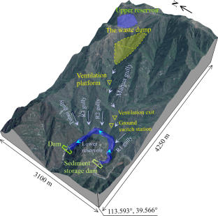
Engineering construction (such as water conservancy project, road engineering, and so on) in mountain areas bring mass of waste soil and rock fragment, whose stability is critical to the ecological environment and the safe operation of engineering facilities. The biggest waste dump of the Pumped Storage Power Station Project in Hunyuan County, Shanxi Province, China, with a volume of 7 million m³ and a maximum height of 240 m, is to be located at the origin of Mahua Valley. To assess the potential risk of the waste dump, reconnaissance, geomorphological analysis was undertaken to provide basic data. The potential failure area and volume was determined utilizing Flac3D depending on strength reduction method. The kinematic process and the potential hazards after failure was presented by Particle flow code. The results showed that the factor of safety of the waste dump under heavy precipitation was 1.15, less than the stability requirement of slope in hydropower station, and the potential failure volume was about 4.8 million m³. The scenario-based debris mass run-out paths indicated that, considering the worst cases scenario, the ground ventilation platform and ventilation tunnel exit on the right bank of the gully might be destroyed rapidly by landslide debris. Besides, the debris flow would accumulate at the gully mouth, and even run into the lower reservoir. Thus, more attention should be taken to increase the stability of the waste dump. These results are useful information for decision support and future hazard assessment of such engineering project.
This is a preview of subscription content, log in via an institution to check access.
Access this article
Price includes VAT (Russian Federation)
Instant access to the full article PDF.
Rent this article via DeepDyve
Institutional subscriptions
Ai J, Chen JF, Rotter JM, Jin YO (2011) Assessment of rolling resistance models in discrete element simulations. Powder Technol 206:269–282
Article CAS Google Scholar
Bao Y, Han X, Chen J, Zhang W, Zhan J, Sun X, Chen M (2019) Numerical assessment of failure potential of a large mine waste dump in Panzhihua City. China Eng Geol 253:171–183. https://doi.org/10.1016/j.enggeo.2019.03.002
Article Google Scholar
Beguería S, Van Asch TWJ, Malet JP, Gröndahl S (2009) A GIS-based numerical model for simulating the kinematics of mud and debris flows over complex terrain. Nat Hazards Earth Syst Sci 9:1897–1909. https://doi.org/10.5194/nhess-9-1897-2009
Blight G (2008) Slope failures in municipal solid waste dumps and landfills: a review Waste management & research. J Int Solid Wastes Public Clean Association ISWA 26:448–463. https://doi.org/10.1177/0734242X07087975
Blight GE, Fourie AB (2005) Catastrophe revisited – disastrous flow failures of mine and municipal solid waste. Geotech Geol Eng 23:219–248. https://doi.org/10.1007/s10706-004-7067-y
Chang K, Taboada A (2009) Discrete element simulation of the Jiufengershan rock-and-soil avalanche triggered by the 1999 Chi-Chi earthquake. Taiwan J Geophys Res 114. https://doi.org/10.1029/2008JF001075
Conte E, Donato A, Troncone A (2016) A simplified method for predicting rainfall-induced mobility of. Act Landslides Landslides 14:1–11
Google Scholar
Cundall PA, Strack ODL (1979) A discrete numerical model for granular assemblies Géotechnique. 29:47–65. https://doi.org/10.1680/geot.1979.29.1.47
De Vita P et al (1998) Rainfall-triggered landslides: a. Ref list Environ Geol 35:219–233. https://doi.org/10.1007/s002540050308
Delaney KB, Evans SG (2015) The 2000 Yigong landslide (Tibetan Plateau), rockslide-dammed lake and outburst flood: review, remote sensing analysis. Process Modelling Geomorphology 246:377–393. https://doi.org/10.1016/j.geomorph.2015.06.020
George D, Iverson R (2011) A two-phase debris-flow model that includes coupled evolution of volume fractions, granular dilatancy, and pore-fluid pressure. https://doi.org/10.4408/IJEGE.2011-03 . B-047
Giani GP (1992) Rock Slope Stability Analysis. A. A. Balkema, Rotterdam, p 361
Itasca CGI (2008) PFC3D particle Flow Code in 3 dimensions. User’s Guide, Minneapolis
Iverson RM (2000) Landslide triggering by rain infiltration. Water Resour Res 36:1897–1910
Iwashita K, Oda M (1998) Rolling resistance at contacts in simulation of shear band development by DEM. J Eng Mech 124:285–292
Iwashita K, Oda M (2000) Micro-deformation mechanism of shear banding process based on modified distinct element method. Powder Technol 109:192–205. https://doi.org/10.1016/S0032-5910(99)00236-3
Kjeldsen P, Fischer E (1995) Landfill Gas Migration–Field investigations at Skellingsted Landfill, Denmark Waste Management & Research -. WASTE MANAGE RES 13:467–484. https://doi.org/10.1177/0734242X9501300506
Kocasoy G, Curi K (1995) The Ümraniye-Hekimbaşi open dump accident Waste Management & Research -. WASTE MANAGE RES 13:305–314. https://doi.org/10.1016/S0734-242X (95)90080-2
Lavigne F et al (2014) The 21 February 2005, catastrophic waste avalanche at Leuwigajah dumpsite, Bandung. Indonesia Geoenvironmental Disasters 1:10. https://doi.org/10.1186/s40677-014-0010-5
Leng Y, Peng J, Wang Q, Meng Z, Huang W (2018) A fluidized landslide occurred in the Loess Plateau: a study on loess landslide. South Jingyang Tableland Eng Geol 236:129–136. https://doi.org/10.1016/j.enggeo.2017.05.006
Liu HD, Li DD, Wang ZF (2018) Dynamic process of the Wenjiagou rock landslide in Sichuan Province. China Arab J Geosci 11:233. https://doi.org/10.1007/s12517-018-3564-9
Lo C-M, Lin M-L, Tang C-L, Hu J-C (2011) A kinematic model of the Hsiaolin landslide calibrated to the morphology of the landslide deposit. Eng Geol 123:22–39. https://doi.org/10.1016/j.enggeo.2011.07.002
Lo C-M, Huang W-K, Lin M-L (2016) Earthquake-induced deep-seated landslide and landscape evolution process at Hungtsaiping, Nantou County. Taiwan Environ Earth Sci 75:645. https://doi.org/10.1007/s12665-016-5474-z
Lu CY, Tang CL, Chan YC, Hu JC, Chi CC (2014) Forecasting landslide hazard by the 3D discrete element method: a case study of the unstable slope in the Lushan hot spring district. Cent Taiwan Eng Geol 183:14–30
Mangeney A, Roche O, Hungr O, Mangold N, Faccanoni G, Lucas A (2010) Erosion and mobility in granular collapse over sloping beds. J Geophys Res Earth Surf 115
Mcdougall S, Hungr O (2004) A model for the analysis of rapid landslide motion across three-dimensional terrain. Can Geotech J 41:1084–1097
Molinari ME, Cannata M, Meisina C (2014) r.massmov: an open-source landslide model for dynamic early warning systems. Nat Hazards 70:1153–1179. https://doi.org/10.1007/s11069-013-0867-8
O’Sullivan C (2011) Particle-based discrete element modeling. Geomech Perspective Int J Geomech 11:449–464
Oda M, Iwashita K, Kakiuchi T (1997) Importance of particle rotation. Mech Granul Mater Powders Grains 97:207–210
Ouyang C, He S, Xu Q, Luo Y, Zhang W (2013) A MacCormack-TVD finite difference method to simulate the mass flow in mountainous terrain with variable computational domain. Comput Geosci 52:1–10. https://doi.org/10.1016/j.cageo.2012.08.024
Ouyang C, He S, Tang C (2015) Numerical analysis of dynamics of debris flow over erodible beds in Wenchuan earthquake-induced area. Eng Geol 194:62–72. https://doi.org/10.1016/j.enggeo.2014.07.012
Ouyang C, Zhou K, Xu Q, Yin J, Peng D, Wang D, Li W (2017) Dynamic analysis and numerical modeling of the 2015 catastrophic landslide of the construction waste landfill at Guangming, Shenzhen. China Landslides 14:705–718. https://doi.org/10.1007/s10346-016-0764-9
Peng J, Ma P, Wang Q, Zhu X, Zhang F, Tong X, Huang W (2018) Interaction between landsliding materials and the underlying erodible bed in a loess flowslide. Eng Geol 234:38–49. https://doi.org/10.1016/j.enggeo.2018.01.001
Poisel R, Preh A (2008) 3D landslide run out modelling using the particle Flow Code PFC3D. In. 873–879. https://doi.org/10.1201/9780203885284-c110
Savage S, Hutter C (1989) The motion of a finite mass of granular material down a rough incline. J Fluid Mech 199:177–215. https://doi.org/10.1017/S0022112089000340
Scaringi G et al (2018) Some considerations on the use of numerical methods to simulate past landslides and possible new failures: the case of the recent Xinmo landslide (Sichuan, China. Landslides 15:1359–1375. https://doi.org/10.1007/s10346-018-0953-9
Xin H, Hanley KJ, O’Sullivan C, Kwok CY (2015) Exploring the influence of interparticle friction on critical state behaviour using. DEM Int J Numer Anal Methods Geomech 38:1276–1297
Xu Q, Peng D, Li W, Dong X, Hu W, Tang M, Liu F (2017) The catastrophic landfill flowslide at Hongao dumpsite on December 20, 2015 in Shenzhen. China Nat Hazards Earth Syst Sci 17:1–19
Zhou J-w, Huang K-x, Shi C, Hao M-h, Guo C-x (2015) Discrete element modeling of the mass movement and loose material supplying the gully process of a debris avalanche in the Bayi Gully. Southwest China J Asian Earth Sci 99:95–111. https://doi.org/10.1016/j.jseaes.2014.12.008
Download references
Acknowledgements
This study is supported by the National Key R & D Projects (NO. 2019YFC1509704), National Natural Science Foundation of China (NO. U1704243), Key scientific research project of colleges and universities in Henan Province (23A410002), The Project of High-level talents in North China University of Water Resource and Electric Power (NO.202010013), Postgraduate Education Reform and Quality Improvement Project of Henan Province(YJS2022JD02, YJS2022AL006).
This study is supported by the National Key R & D Projects (NO. 2019YFC1509704), National Natural Science Foundation of China (NO. U1704243), Key scientific research project of colleges and universities in Henan Province(23A410002), The Project of High-level talents in North China University of Water Resource and Electric Power (NO.202010013), Postgraduate Education Reform and Quality Improvement Project of Henan Province(YJS2022JD02、YJS2022AL006).
Author information
Authors and affiliations.
North China University of Water Resources and Electric Power, Zhengzhou, 450045, China
Dong-dong Li, Han-dong Liu & Zhong-fu Wang
Qinghai Nonferrous third Geological Exploration Institute, Xining, 810000, China
Feng-lan Chen
Power Construction Corporation of China Jiangxi Electric Power Design Institute CO., LTD, Nanchang, 330096, China
Xiao-chao Li
You can also search for this author in PubMed Google Scholar
Corresponding author
Correspondence to Dong-dong Li .
Ethics declarations
Conflict of interest.
No conflict of interest exits in the submission of this manuscript, and manuscript is approved by all authors for publication. I would like to declare on behalf of my co-authors that the work described was original research that has not been published previously, and not under consideration for publication elsewhere, in whole or in part. All the authors listed have approved the manuscript that is enclosed.
Additional information
Publisher’s note.
Springer Nature remains neutral with regard to jurisdictional claims in published maps and institutional affiliations.
Rights and permissions
Springer Nature or its licensor (e.g. a society or other partner) holds exclusive rights to this article under a publishing agreement with the author(s) or other rightsholder(s); author self-archiving of the accepted manuscript version of this article is solely governed by the terms of such publishing agreement and applicable law.
Reprints and permissions
About this article
Li, Dd., Liu, Hd., Wang, Zf. et al. Potential risk assessment of the large hydropower station dumpsite using numerical simulation: a case study in Shanxi Province, China. Nat Hazards (2024). https://doi.org/10.1007/s11069-024-06505-4
Download citation
Received : 15 July 2023
Accepted : 14 February 2024
Published : 03 April 2024
DOI : https://doi.org/10.1007/s11069-024-06505-4
Share this article
Anyone you share the following link with will be able to read this content:
Sorry, a shareable link is not currently available for this article.
Provided by the Springer Nature SharedIt content-sharing initiative
- Waste dumpsite
- Potential risk assessment
- Discrete element model
- Kinematic process
- Find a journal
- Publish with us
- Track your research
IMAGES
VIDEO
COMMENTS
A case study on failure of AISI 347H stabilized stainless steel pipe in a petrochemical plant. M. Ghalambaz, ... A. Bahrami. October 2017 View PDF. Short communicationOpen access.
Case Studies in Engineering Failure Analysis. Open access. Articles & Issues. Menu. Articles & Issues. Latest issue; All issues; Submit search. Volume 1, Issue 1 Pages 1-48 (January 2013) Download full issue. Previous vol/issue. Next vol/issue. Actions for selected articles. Select all / Deselect all.
Like Engineering Failure Analysis, it will publish interesting case studies of engineering failures, but whilst EFA concentrates of publishing novel and substantial papers, CSEFA will concentrate ...
Introduction. Failure analysis of complex systems always requires an interdisciplinary approach to identify and sort out, which influences contributed to the failure of a component. Normally, the failure mechanism(s) may be established by different material investigations, reflecting the detrimental influences (mechanical, thermal, chemical, tribological loads), reference to Fig. 3.1 in Chap ...
the fatigue cracks. Crack 1 is the oldest fatigue crack and is therefore used for analysis. Case Studies in Engineering Failure Analysis 5-6 (2016) 39-50 A R T I C L E I N F O Article blades history: Received 15 December 2015 Received in revised form 11 January 2016 Accepted 8 February 2016 Available online 15 February 2016 Keywords ...
Bhagi et al./Case Studies in Engineering Failure Analysis 1 (2013) 72-78 75. EDS analysis at the fractured part of the blade detected ample amount of Si along with O, K, Al, Na and S (Fig. 8). The presence of these nonmetallicinclusions at the fracturedsurface indicates long term exposure in theatmosphere or the
Hoan bridge failure in Milwau-kee, Wisconsin in 2000; partially collapse of Cosen bridge in Latchford, Canada in 2003 and etc. The detailed inspections of steel truss bridges in the word revealed damages such as cracks and fractures, Case Studies in Engineering Failure Analysis 4 (2015) 50-58 A R T I C L E I N F O Article and history ...
In the present research, failure analysis of a failed interfering journal bearing part of a steam power plant turbine was assessed and failure mechanism determined by monitoring of the metallurgical characteristics and failure features through different microstructural and mechanical experiments. 2. Materials and methods.
The three case studies discussed in this chapter have clearly shown us that finite element analysis (FEA) is an excellent and powerful tool that can be employed in failure analysis. Finite element analysis provides a failure analyst with more quantitative and qualitative information about the causes of failure.
Failure Analysis "Red Herrings". December 2008 · AM&P Technical Articles. P.H. DeVries. This article is based on Four Red Herrings, Float Switch Failure, and a Case of Multiple Failure Scenarios ...
Description. The first book of Failure Analysis Case Studies selected from volumes 1, 2 and 3 of the journal Engineering Failure Analysis was published by Elsevier Science in September 1998. The book has proved to be a sought-after and widely used source of reference material to help people avoid or analyse engineering failures, design and ...
the second included the analysis of the stress, the torsional resonance and the shaft's design. Case Studies in Engineering Failure Analysis 5-6 (2016) 51-58 A R T I C L E I N F O Article ...
The shaft analyzed (replacement part) belongs to a bridge crane fractured after one year of operation. Fundamentally, the bridge crane system consists of an electric motor that transmits power to the shaft and this shaft transmits power to a reducer gearbox; a representation of the system is shown in Fig. 1. The keyway connects the system's ...
2013 — Volume 1. Title discontinued as of 2018; ISSN: 2213-2902. Read the latest articles of Case Studies in Engineering Failure Analysis at ScienceDirect.com, Elsevier's leading platform of peer-reviewed scholarly literature.
Case Studies in Engineering Failure Analysis will build on the excellent work already done by journals such as Engineering Failure Analysis. Like Engineering Failure Analysis, it will publish interesting case studies of engineering failures, but whilst EFA concentrates of publishing novel and substantial papers, CSEFA will concentrate of ...
The paper is devoted to creating a methodological approach to apply root cause analysis for solving the specific materials science task. The case study determined the causes of the destruction of the elements of the exhaust tract of the gas pumping unit. Root cause...
Further, it is unusual for a failure analysis study to include a description of the legal aspects of the case. Yet for the individual or organization involved in a product liability case, as plaintiff or defendant, the blend of the legal and the technical is extremely important. The combination is called forensic engineering.
MTI lead on-site rep presented charts leading to first (engineering) recommendation: "O-Ring temp must be 53 degF (or greater) at launch." NASA on-site reps asked for and got MTI higher management telecom concurrence. After off-line conference, top management in Utah withdrew earlier objection.
122 Haghshenas, R.J. Klassen/Case Studies in Engineering Failure Analysis 2 (2014) 118-126. 3. Factors contributing to the fatigue failure The origin of the premature fatigue fracture of splined regions of the mandrel was attributed to one or a combination of the followings: 3.1.
The results of finite element analysis show that the state of stress is strongly affected by the condition of the chain installed in the hook, due to the fact that the stress magnitude caused by bending forces is 2.5 times greater than that of the plain tensile load. FEA results are in accordance with the fractographic analysis, in that the ...
There are three ways to introduce failure analysis and failure case studies into civil engineering education. A small number of colleges and universities, probably only a few percent, offer courses in forensic engineering or failure case studies. Often, these are at institutions such as the University of Texas, Mississippi State University, or ...
Engineers evaluate the failures, and they update the engineering codes so that they better account for the effects of ship collisions. Cargo ship loses power, crashes into the Francis Scott Key ...
The safety risk analysis of urban elevated bridge construction is an important management method to reduce the loss of safety accidents, and it has significant scientific research value and engineering application value. Therefore, this study proposes a novel analysis method to address these challenges. Firstly, this paper constructs a Work Breakdown Structure (WBS)-Risk Breakdown Structure ...
Slip-buckling failure is a common occurrence in bedding rock slopes, and it can be triggered by long-term gravitational stress, earthquakes, top loading and intense rainfall. In this paper, an analytical solution is proposed to address the slip-buckling failure of bedding rock slopes under the influences of top loading and earthquakes based on mechanical analysis and energy equilibrium theory ...
Published: March 26, 2024 11:59pm EDT. When the container ship MV Dali, 300 metres long and massing around 100,000 tonnes, lost power and slammed into one of the support piers of the Francis Scott ...
Final citation details, e.g. volume and/or issue number, publication year and page numbers, still need to be added and the text might change before final publication. ISSN: 2213-2902. Read the latest articles of Case Studies in Engineering Failure Analysis at ScienceDirect.com, Elsevier's leading platform of peer-reviewed scholarly literature.
Barzin Mobasher, a structural engineering professor at Arizona State University, similarly told CNN the collapse was a matter of physics: Once the ship hit one of the bridge's columns, it ...
Engineering construction (such as water conservancy project, road engineering, and so on) in mountain areas bring mass of waste soil and rock fragment, whose stability is critical to the ecological environment and the safe operation of engineering facilities. The biggest waste dump of the Pumped Storage Power Station Project in Hunyuan County, Shanxi Province, China, with a volume of 7 million ...